Download
1 / 24
240 likes | 267 Views
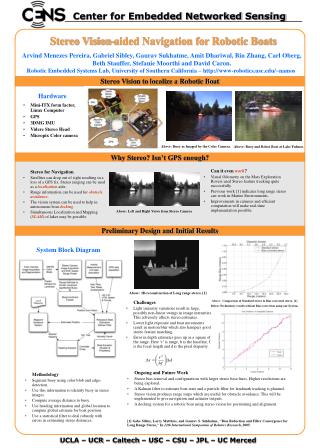
Robotic Navigation Distance Control Platform. By: Scott Sendra Advisors: Dr. Donald R. Schertz Dr. Aleksander Malinowski March 9, 2004. Overview. Objective Functional Description System Block Diagrams Lab Work Equipment/Part List Original Schedule of Tasks Tasks Completed

E N D
Robotic Navigation Distance Control Platform By: Scott Sendra Advisors: Dr. Donald R. Schertz Dr. Aleksander Malinowski March 9, 2004
Overview • Objective • Functional Description • System Block Diagrams • Lab Work • Equipment/Part List • Original Schedule of Tasks • Tasks Completed • Remaining Task to be Completed • Revised Schedule of Tasks
Objective • Design and Build a Robotic Platform • Maintain a fixed safety distance • Fixed steering
Functional Description • Modes of Operation • System I/O • System Diagrams
Modes of Operation Fixed Navigation Mode • User enters User or Auto Out of Range Modes • User enters fixed safety distance in feet • User presses activation button Time Navigation Mode • User enters safety time in seconds
Modes of Operation User Out of Range Mode • Followed object is out of range • Robotic platform stops • “Out of Range” displayed on LCD • User reactivates navigation controls • Clears LCD display Auto Out of Range Mode • EMAC reactivates navigation controls when object detected
Modes of Operation Stop/Start Mode • User is able to start/stop navigation mode manually
System Inputs to EMAC Robotic Platform Motor User Input • Keypad Sensors Input • SRF04 ultrasonic sensors • 1 sensor for distance control Keypad (User Input) Distance Control Sensor EMAC Microcontroller Robotic Platform Steering LCD Display
System Outputs from EMAC • LCD Display • Current mode of operation • User required input information • Robotic Platform Motor • Robotic Platform Steering Robotic Platform Motor Keypad (User Input) Distance Control Sensor EMAC Microcontroller Robotic Platform Steering LCD Display
System Sensor Diagram Robotic Platform (R/C Car) Moving Object (Similar size to robotic platform) Distance Sensor
Block Diagram Hardware • Subsystem Function • I/O of Subsystem Software • Modes of Operation Flowcharts
Sensor Subsystem • SRF04 Ultrasonic Pulse Sensor • Sensor Output Signals • Output signal related to distance • PWM at 33 Hz
Electric Motor Subsystem Input signal • PWM signal from 1.0 ms to 1.7 ms positive pulse width at 33 Hz Output speed • Motor’s shaft speed varies • Full forward speed with 1.7 ms pulse width • Stop with 1.0 ms pulse width
Steering Subsystem Input signal • PWM signal from 1.1 ms to 1.9 ms positive pulse width at 50 Hz with 1.5 ms as neutral Output • Rotational servo horn to translational movement of steering rod
Hardware Subsystem Block Diagram EMAC Microcontroller Power to Drive Wheels on R/C Car Robotic Platform Motor Subsystem PWM Signal Analog or Digital or PWM Signal Photoelectric or Ultrasonic Pulse Distance Control Sensor Subsystem Robotic Platform Steering Subsystem Translates Steering Rod PWM Signal
Main Software Flowchart EMAC Initialization LCD Initialization Keypad Initialization Display Prompt: Fixed/Time Navigation Mode Keypad: User Enters Navigation Mode Keypad: User enters fixed distance or safety time Display Prompt: User/Auto Out of Range Mode Keypad: User Enters Out of Range Mode
Main Software Flowchart Keypad: Activation Button Check if signal from sensor No Enter User/Auto Out of Range Mode Yes Steering Control Time Navigation Mode entered Fixed Navigation Mode entered Check navigation mode entered Fixed Distance Control Safety Time Control
User/Auto Out of Range Mode Display: User/Auto Out of Range Mode Stop Electric Motor User Out of Range Mode Auto Out of Range Mode Wait: User Reactive Navigation Controls Auto: Wait until object is detected Display: Clear display Call Fixed/Time Navigation Mode User/Auto Flowchart
Start/Stop Flowchart Keypad: User Presses Stop Button Keypad: User Presses Start Button Stop Electric Motor Call Fixed/Time Navigation Mode
ESC Lab Work • Servo input signals with 1.5 ms at 33 Hz being neutral • Full understand of ESC required signal inputs • Rooster ESC reprogrammed • Reprogrammed : 1.0 ms stop 1.7 ms full forward • Servo, ESC and Ultrasonic signals programmed
Equipment and Parts List • Hitec HS-303 Servo • Kyosho Hoppin Mad RTR R/C Car • Team Novak Rooster electronic speed controller • HP 8011A Pulse Generator • SRF04 Ultrasonic pulse sensors • Onboard 80515 EMAC Microcontroller
Original Schedule of Tasks 12/22 – 1/27 Determine sensors 1/28 – 2/03 Motor and servo subsystem coding, debugging and testing 2/04 – 2/10 Stop/Start Mode software coding, debugging and testing 2/11 – 2/17 2/18 – 2/24 User input software code, debugging and testing 2/25 – 3/02 3/03 – 3/09 Sensor characteristic and output signals 3/10 – 3/16 Hardware interfacing and installation 3/17 – 3/23 3/24 – 3/30 3/31 – 4/06 4/07 – 4/13 4/14 – 4/20 4/21 – 4/27 4/28 – 5/04 Finish project, presentation, project report Fixed navigation mode software code, debugging and testing User/Auto Out of Range mode software code, debugging and testing
Revised Schedule of Tasks 3/03 – 3/09 3/10 – 3/16 3/17 – 3/23 3/24 – 3/30 Start Mode software coding, debugging and testing 3/31 – 4/06 4/07 – 4/13 4/14 – 4/20 4/21 – 4/27 Hardware interfacing and installation 4/28 – 5/04 Finish project, presentation, project report Fixed navigation mode software code, debugging and testing User/Auto Out of Range mode software code, debugging and testing User input software code, debugging and testing