Download
1 / 6
60 likes | 161 Views
Explore the critical parameters and functions of phase and frequency modulation using VCOs and phase shift in this comprehensive guide. Learn about modulation sensitivity, phase deviation, and critical modulation sensitivity for precise signal demodulation. Dive into the principles of VCO operation and phase modulation techniques.

E N D
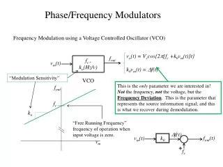
Phase/Frequency Modulators Frequency Modulation using a Voltage Controlled Oscillator (VCO) vo(t) = Vccos{2p[fc +k0vm(t)]t} k0vm(t) = Df(t) fout fc , ko(Hz/v) VCO vm(t) “Modulation Sensitivity” This is the only parameter we are interested in! Not the frequency, not the voltage, but the Frequency Deviation. This is the parameter that represents the source information signal; and this is what we recover during demodulation. fout fc ko “Free Running Frequency” frequency of operation when input voltage is zero. Df(t) fout(t) vm(t) k0 vm + fc
Phase/Frequency Modulators Reference Phase Phase Modulation using a Voltage Controlled Phase Shift fc vo(t) = Vccos{2pfct+kpvm(t)} kpvm(t) = F(t) vm(t) kp(rad/v) “Modulation Sensitivity” Phase Deviation F This is the only parameter we are interested in! Not the frequency, not the voltage, but the Phase Deviation. This is the parameter that represents the source information signal; and this is what we recover during demodulation. vm
Determining Modulation Sensitivity for a Phase Modulator Reference Phase V(t)=I0ZT(t)) = V ejq(t) = V ej(wt+F(t)) i(t)=I0cos(wct) Phase Deviation
Chain Rule v0 is the DC bias level which gives zero phase shift. When v0 is applied to the diode: C(v0) = C0(1+2v0)-1/2 = Cc w(v0)= wc S(v0) = 0
Limit of Linearity: How good is good enough? DF s se Phase Error DFe se s For a maximum fractional error (distortion) of e, the maximum normalized frequency displacement is: 1 If e < 0.05, DFMAX < 0.39R