Group Technology
GT. Group Technology. Job shop production System Batch production System Mass production System. Group Technology.

Group Technology
E N D
Presentation Transcript
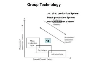
GT Group Technology Job shop production System Batch production System Mass production System
Group Technology Group technology (GT) is a manufacturing philosophy that seeks to improve productivity by grouping parts and products with similar characteristics into families and forming production cells with a group of dissimilar machines and processes. The group of similar parts is known as part family and the group of machineries used to process an individual part family is known as machine cell. It is not necessary for each part of a part family to be processed by every machine of corresponding machine cell.
Group Technology Group technology begun by grouping parts into families, based on their attributes (Geometry, manufacturing process ). Geometric classification of families is normally based on size and shape, while production process classification is based on the type, sequence, and number of operations. The type of operation is determined by such things as the method of processing, the method of holding the part, the tooling. There are three methods that can be used to form part families: • Manual visual inspection • Production flow analysis • Classification and coding Manual visual inspection involves arranging a set of parts into groups by visually inspecting the physical characteristics of the parts.
Part Family 1 Part Family 2 Manual visual inspection
Production flow analysis: Parts that go through commonoperations are grouped into part families. The machines used to perform these common operations may be grouped as a cell, consequently this technique can be used in facility layout (factory layout)
Rank Order Clustering Algorithm: Rank Order Clustering Algorithmis a simple algorithm used to form machine-part groups. Step 1: Assign binary weight and calculate a decimal weight for each row. Step 2: Rank the rows in order of decreasing decimal weight values. Step 3: Repeat steps 1 and 2 for each column. Step 4: Continue preceding steps until there is no change in the position of each element in the row and the column.
Example #1 Consider a problem of 5 machines and 6 parts. Try to group them by using Rank Order Clustering Algorithm.
Step 1: Step 2: Must Reorder!
Step 3: Step 4: Must Reorder
Back at Step 1: Order stays the same: STOP!
Example #2 Step 1: Assign binary weight and calculate a decimal weight for each row
Example #2 Step 3: Reorder the matrix according to rank
Example #2 Step 4: Assign binary weight and calculate a decimal weight for each Column
Example #2 Step 5: Reorder the matrix according to rank
Example #2 Repeat Step 1&2: Assign binary weight and calculate a decimal weight for each row Order stays the same:
Example #2 Repeat Step 4 & 5 Order stays the same: STOP!
Voids Exceptional parts Solutions for overcoming this problem? • Duplicate machines • Alternate process plans • Subcontract these operations Example #2 Part family 1: Part Nos. 1, 4, 2 & 7 Machine Cell 1: C, D & A Part family 2: Part Nos. 3, 5, and 5 Machine Cell 2: E & B No. of exceptional Parts: 3 No. of Voids: 5 No. of bottleneck machines: 2(Machines D & E)
Duplicate machines No. of exceptional Parts: 3 No. of Voids: 5 No. of bottleneck machines: 2(Machines D & E) No. of exceptional Parts: 0 No. of Voids: 9 No. of bottleneck machines: 0 No. of duplicate machine: 2(Machines D & E
Alternate process plans No. of exceptional Parts: 3 No. of Voids: 5 No. of bottleneck machines: 2(Machines D & E) No. of exceptional Parts: 2 No. of Voids: 3 No. of bottleneck machines: 2(Machines D & E
Step 1: Step 2: Must Reorder!
Step 3: Step 4: Must Reorder
Back at Step 1: Step 2: Must Reorder
Back at Step 1: Step 2: Must Reorder
Clustering Methods • Using Process Similarity methods: • Create Machine – Part Matrices • Compute machine ‘pair-wise’ similarity Coefficient comparisons:
Computing Similarity Coefficients: • Total number of coefficient is: • [(N-1)N]/2 = [(5-1)5]/2 = 10 • For 25 machines (typical number in a small Job Shop): 300 Sij’s
A C D E B 0.33 Grouping of parts using Clustering Methods Similarity coefficients of machine pairs 0.67 0 Dendrogram
Classification and Coding • Codingrefers to the process of assigning symbols to the parts • The symbolsrepresent design attributes of parts or manufacturing features of part families • Although well over 100 classification and coding systems have been developed for group technology applications, all of them can be grouped into three basic types: • Monocode or hierarchical code • Polycode or attribute • Hybrid or mixed code
MONOCODE (HIERARCHICAL CODE) • This coding system was originally developed for biological classification in 18th century. • In this type of code, the meaning of each character is dependent on the meaning of the previouscharacter; that is, each character amplifies the information of the previous character. Such a codingsystem can be depicted using a tree structure Monocode of Fig. 1: A-1-1-B-2 Fig. 1 Spur gear
POLYCODE (ATTRIBUTE CODE): • The code symbols are independent of each other • Each digit in specific location of the code describes a unique property of the workpiece • it is easy to learn and useful in manufacturing situations where the manufacturing process have to be described • the length of a polycode may become excessive because of its unlimited combinational features
POLYCODE (ATTRIBUTE CODE): Polycode for the spur gear (Fig. 1): 22213
MIXED CODE (HYBRID CODE): • In reality, most coding systems use a hybrid (mixed) code so that the advantages of each type of system can be utilized. The first digit for example, might be used to denote the type of part, such as gear. The next five position might be reserved for a short attribute code that would describe the attribute of the gear. The next digit (7th digit) might be used to designate another subgroup, such as material, followed by another attribute code that would describe the attributes.