Download

1 / 19
190 likes | 205 Views
This study discusses the positioning system of the Antares telescope and explores ideas and studies for scaling it to the KM3NeT project. It examines the acoustic-optical positioning system and proposes potential improvements.

E N D
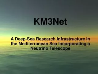
Some preliminary studies for the positioning calibration of KM3NeT MiguelArdid Universitat Politècnica de València
Contents • Introduction • Positioning system of Antares • Ideas and studies for KM3NeT • ANTARES system scaled to KM3NeT • Acoustic-optical positioning system • Conclusion and discussion
Introduction • A positioning system for the optical modules is needed: • A rigid structure would be much more difficult to deploy • Water current flow shifts the OM positions several meters • Difficulties of the system: • Deep water, large volume, number of elements, integration in the telescope. • Combined in a system with a reasonable cost and complexity • Large uncertainty in the description of the detector: • mechanics, optic modules, line spacing, etc.? • specifications for calibration (position resolution needed?)
Positioning system of Antares • ANTARES has a positioning system to determine the exact position of the optical modules and monitor them continuously. It is based in the reconstruction of the shape of the line from the information of: • High frequency long baseline (LBL) acoustic system, which has transponders and emitters anchored in the lines and hydrophones on detector strings: • Gives the positions of these elements in the line • Tiltmeters and Compasses: • Give the local tilt angles of each OM storey • plus instrumentation necessary to determine the sound velocity in sea water and the water current flow (which can affect the positioning system data)
Inclination of line results from buoyancy P and horizontal force F due to sea current: height in m z N N tanF /P j j P i i r j=i j=i zenith angle i P = buoyancy – weight F = 1/2 cw A v j sea current v F i 2 j j j of element j of the line tandr/dz i integration Line shape: displacement in m r(z) = a v z - b v ln[1-cz] 2 2 the only unknown is sea current velocity v a, b, c known constants Positioning system of Antares: Line reconstruction
Positioning system of Antares: Line reconstruction • Input: • Positions from hydrophones • Tilts and Heading from Compass/Tiltmeter • Geometrical Constants (cable length, storey parameters etc.) • Output: • Positions of all Storeys • Storey orientation as Euler angles (alpha, beta, gamma)
Positioning system of Antares: Acoustic system Triangulisation: Acoustic distance measurement of hydrophones of the line from fixed emitters on the lines anchor + autonomous transponders
Positioning system of Antares: Acoustic system Tracking of hydrophone (from V. Bertin and G. Lelaizant, CPPM) Line 1 hydrophones Acoustic distance measurement of hydrophones from fixed emitters on the lines anchor + autonomous transponders AutonomousTransponder
Positioning system of Antares: Line reconstruction • Line reconstruction with tiltmeters/compasses compared to hydrophone position (from H. Motz, Erlangen)
Ideas and studies for KM3NeT • ANTARES system scaled to KM3NeT • Scaled ANTARES system • Not so close ANTARES system • Far away from ANTARES system • Acoustic-optical positioning system • Geometric assumptions • Position resolution as a function of timing resolution • Expected photoelectron distribution • Future studies
ANTARES system scaled to KM3NeT • In order to scale the ANTARES system: • Reduce substantially the number of acoustic emitters (not for all the lines) ( 1/5) • Larger distances lower frequency • Hydrophones: reduce the unit price • Try to reduce the number of tiltmeters and compasses ( 50%) + reduction of the unit price • Now, we have the ANTARES experience and we are close to fully understand its positioning system: good situation for the evaluation of these possibilities for KM3NeT
ANTARES system scaled to KM3NeT • Not so close to the ANTARES system: • Fewer emitters Larger distances lower frequency worse time accuracy worse position resolution • In order to overcome this: • Optimization of algorisms and signal processing for both signal detection and position reconstruction • Wideband technology instead of using tone signals. • We have tried with different calibration signals: • MLS (Maximum Length Sequences): not working very well with piezoelectrics • TSP (Time Stretched Pulses): it is possible to have good positioning at lower frequencies (less attenuation)
ANTARES system scaled to KM3NeT • Far away from the ANTARES system: • Hydrophones: reduce the unit price • Piezos glued to Antares sphere?: • Erlangen has shown that they can be used for acoustic detection of neutrinos, Astropart. Phys. 26 (2006) 301. • For acoustic positioning should be much easier. • Optic module with piezo?: • Advantages: direct position of the optic module, compasses and tiltmeters probably not needed • Drawbacks: more R&D needed (be sure that the optic system do not interfere with the acoustic one and viceversa), more electronics
Acoustic-optical positioning system • Since an optic system is necessary to calibrate the photomultipliers, the idea is to include them in the positioning system • A two step system: • Photomultipliers are located with optic calibrators, and these ones by acoustics Optic Modules ~300 m ~ 1000 m ~150 m AutonomousTransponder Optic Beacon + Acoustic Receiver
Acoustic-optical positioning system • Simulations and study done by J. Hößl, Erlangen • Geometric assumptions: • The mechanics are similar to those of ANTARES • Detection lines (hor. spacing 120 m) with optic modules (vertical spacing 60 m) • Calibration lines (hor. spacing 360 m) with LED Beacons (vertical spacing 300 m) • Downward looking optic modules
0.5 ns 25 cm Acoustic-optical positioning system • Position resolution as a function of timing resolution: • assuming that all time calibrations were already performed and there are no unknown time-offsets
Acoustic-optical positioning system • Expected photoelectron time distributions at different distances from the LED beacon accumulated in 5000 shots (1 second) • ANTARES LED beacons, but with 10 times more intensity. • Each beacon contains 36 blue LEDs (470 nm average wavelength, rise-time around 2 ns, FWHM of 6 ns)
Acoustic-optical positioning system • Future studies: • Can the position resolution be improved by line reconstruction model? • Reconstructing the shape of the line using the positions obtained from the optical triangulation, the geometrical constants and the weight and drag coefficients of all elements with the sea current velocity as the only free parameter • If possible, to check the viability of this system in the ANTARES telescope: • comparing the positions obtained with the optic calibration with those of the positioning system
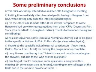
Conclusions and discussion • Fortunately, it seems that there are possible good solutions for the positioning system of KM3NeT and several ideas have been reported : • From more conservative (a scaling of the ANTARES positioning system) to more risky (piezos glued in the optic modules or acoustic-optical positioning system) • However, the problem is still too much open to determine the best solution and work for it, especially if one bets for a risky solution • Time for discussion in order to define the telescope as much as possible and to arrange working groups in order to determine the feasibility of the solutions proposed