Download
1 / 40
400 likes | 418 Views
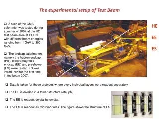
The DAFNE BTF is a high current e-/e+ test beam facility in the Frascati DAFNE collider complex. It is a multi-purpose facility that allows for detector testing, beam tuning, and beam energy tuning.

E N D
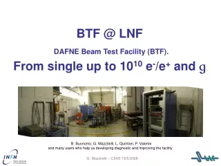
BTF @ LNFDAFNE Beam Test Facility (BTF).From single up to 1010 e-/e+ and g B. Buonomo, G. Mazzitelli, L. Quintieri, P. Valenteand many users who help us developing diagnostic and improving the facility G. Mazzitelli – CSN5 19/5/2008
BTF • high current Linac: • 1 - 500 mA e- 200 mA e+, • 1 - 10 ns pulses, at least 107 particles The DAFNE BTF The BTF is a e-/e+test-beam facility in the Frascati DAFNE collider complex Need to attenuate the primary beam: • Single particle regime is ideal for detector testing purposes • Allows to tune the beam intensity • Allows to tune the beam energy G. Mazzitelli – CSN5 19/5/2008
control room 5.5 m 4 m Hall BTF Hall BTF layout LINAC tunnel momentum analyzer main ring G. Mazzitelli – CSN5 19/5/2008
0 1e- 2e- 3e- detector LINAC Beam 1-500 mA W slits N. of particles 450 magnet Selected energy (MeV) LINAC beam attenuation 103 102 10 1 0 100 300 500 tunable Cu target: 1.7, 2.0, 2.3 X0 G. Mazzitelli – CSN5 19/5/2008
BTF beam characteristic Beam (e- or e+) intensity can be adjusted by means of the energy dispersion and collimators, down to single particle per pulses Number (particles/pulse) 1105 11010 Energy (MeV) 25-500 25750 Repetition rate (Hz) 20-50 50 Pulse Duration (ns) 10 1 or 10 p resolution 1% Spot size (mm)sx,y ≈ 2 (single particle) up to 10*10 (high multiplicity) Divergence (mmrad) s’x,y ≈ 2 (single particle) up to 10 (high multiplicity) • Multi-purpose facility: • H.E. detector calibration and setup • Low energy calorimetry & resolution • Low energy electromagnetic interaction studies • High multiplicity efficiency • Detectors aging and efficiency • Beam diagnostics G. Mazzitelli – CSN5 19/5/2008
DAFNE-L BTF Operation … The BTF in in operation since 2003 beam is delivered 24 h/day with an efficiency of 96% but when parassiting DAFNE main operation the duty cycle was degraded ~ 45% due to continuous injection into the main ring. In 2006 a fast pulsed power supply has been installed increasing the duty cycle up ~ 90%. beam request in last 4 years(multi users are counted twice) 2007 - 224 days 2006 - 244 days 2005 - 364 days 2004 - 282 days 2006-2007 DAFNE run users requests 2008 - 124 days up to end of June G. Mazzitelli – CSN5 19/5/2008
Present RUN 148 days allocated over 175 of operation, typical real access 80-90% of allocated time G. Mazzitelli – CSN5 19/5/2008
5.5 m 4 m Linac tunnel Equipment: infrastructure • one meeting room (WiFi) • one guest office (LAN-WiFi) Control room: Pc’s, Controls console, printercabling, crate and racks, etc main entrance: radioprotection wallcan be removed on demand G. Mazzitelli – CSN5 19/5/2008
Equipment: infrastructure • permanent DAQ TDC/QDC/ADC/scaler/disc. available • NIM, VME, CAMAC Branch, VME controllers • ‘Devil’/VMIC VME and CAMACcontroller, NIM modules • Remotely controlled trolley • Gas system • HV system… • crates, rack, etc. Noble Gas C2H6 CO2 C4H10 • HV SY2527 (3/4KV neg, 3/4KV pos, 15KV pos) • 40 ch. CAEN SY127 pos. • Cabling BTF HALL-BTF CR • Network: Wi-Fi, dedicated-LAN, WAN, printer http://www.lnf.infn.it/acceleratori/btf/ G. Mazzitelli – CSN5 19/5/2008
Equipment: Diagnostics low multiplicity diagnostic (1-100): (back detector) • lead glass, 5×5×35 - 10×10×35 cm • PbWO4 crystal 3*3*11 cm • lead/scintillator fibers (KLOE type), 25×50×30 cm • NaI high resolution 30×30 cm (front/trigger detector/not destructive/tracking) • multipurpose plastic scintillators 10x10x0.5 cm, 10x30x0.5 cm,1x15x0,5 cm • hodoscope; two bundle of 1 mm fiber for a total active area of 48x48 mm2 • Silicon tracker (high gain) • 3GEM (Gas Electron Multiplier) detector 2×2 mm spot size in fiber hodoscope 2×2 mm spot size in Silicon XY chamber G. Mazzitelli – CSN5 19/5/2008
50 MeV Calorimetric counting number of produced electrons counted by total energy deposited in lead/scintillating fiber calorimeter (KLOE type): limited to few tens of MeV, due to energy resolution limited to few tens of particles, due to saturation effects • calorimetric is OK at low intensity, not for high multiplicity beams: e.g. the AIRFLY experiment, designed to measure absolute fluorescence yield in air and its energy dependence, needs: • full energy range • maximum beam intensity G. Mazzitelli – CSN5 19/5/2008
Defocused Beam spot measured with all transfer line quadrupoles off: 5535 mm2, limited by vacuum pipe section Beam profile (AGILE Si tracker) 2 layers (x,y) 384 strips, analog readout 410 mm thick, single-side, AC coupled strips, 121 mm pitch,242 mm readout pitch Optimal focusing at 493 MeV, measured spot size: s 2 2 mm2 G. Mazzitelli – CSN5 19/5/2008
Sci-fi profile detector • A permanent beam position and size monitor needed, both for beam steering and optimization purposes, and for providing useful information for detector testing, complementing the beam intensity monitors • Such a position sensitive detector should have: • negligible mass, not to spoil beam characteristics (energy, divergence, spot size) • good resolution, as compared to beam typical size (1 mm required) • sensitivity both for single particle (even at low energy) and at high beam intensity • 4 layers of fibers glued together • staggered by ½ fiber to minimize dead zones cladded scintillating fibers, Pol.Hi.Tech type 0046, 1 mm diameter G. Mazzitelli – CSN5 19/5/2008
energy dependence of the beam spot size H size (mm) E (MeV) Consistent with beam image from Silicon tracker Sci-fi profile detector • Charge weighted profiles for x and y fiber bundles y (mm) x (mm) G. Mazzitelli – CSN5 19/5/2008
Examples of experimental setup (P326 Prototype inefficiency 200 MeV) energy spectrum inefficiency VS threshold - no tagging- tagging - tagging loose - FC max- N/Ntot- FC min G. Mazzitelli – CSN5 19/5/2008
beam exit sci-fi profile detector detector (MEG test for sci time resolution) back detector (NaI calorimeter) on line monitor e- spectra XY beam sci-profile Example of experimental setup (MEG) G. Mazzitelli – CSN5 19/5/2008
BTF photon tagged sourceAGILE GRID photon calibration The AGILE Gamma Ray Imaging Detector calibration at BTF is aimed at obtaining detailed data on all possible geometries and conditions. BTF can provide data in the most significant energy region (20-700 MeV) spectrometer silicon detector silicon tagging target AGILE GRID Be window G. Mazzitelli – CSN5 19/5/2008
gtagging @ BTF position and direction of the in-coming electrons x2 y2 x1 y1 Nominal B field e- G. Mazzitelli – CSN5 19/5/2008
gtagging @ BTF position and momentum of theout-coming electrons Nota bene Online plots, analysis in progress Increase B field G. Mazzitelli – CSN5 19/5/2008
Equipment: Diagnostics (con’t) • medium multiplicity diagnostic (100-108): (front detector/not destructive) • Cerenkov light emission • Silicon Beam Chamber (low and tunable gain) • Triple GEM TPC (under development) • high multiplicity diagnostic (107-1010): (front detector) • low noise (3×10⁶ particles) BCM • high sensitivity fluorescence flags – cromox, Be, yag:ce G. Mazzitelli – CSN5 19/5/2008
Cerenkov beam monitor detector, designed and built, in collaboration with the AIRFLY group, based on Cerenkov light emission • Cross-calibrated with calorimetric measurement at low particle multiplicity • Used to monitor beam intensity at higher intensity up 104105 particles, in the full energy range • filter • PMT dynamical range can be further extended: • calibrated optical filter in front of the PMT • use air as Cerenkov radiator detector tested up to 1010 particles with a cross calibration with BCM • 45o mirror • Plexiglas radiator G. Mazzitelli – CSN5 19/5/2008
Cerenkov beam monitor :10 optical filter (measured attenuation = 0.096) Calorimeter Calorimeter Cerenkov/Calorimeter ratio No optical filter Calorimeter Calorimeter Cerenkov/Calorimeter ratio Calorimeter/Cerenkov calibration G. Mazzitelli – CSN5 19/5/2008
Compact-Triple Projection GEM It’s essentially a small TPC with a 3-4 cm drift Also high current beam can be monitored in position (TDC) and dE/dX (ADC) box cross section BTF beam ASDQ or Carioca GEM 16 samples for each readout The detector will be realized with standard 10x10 cm2 GEMs inside a G10 box; the readout will be realized with - ASDQ (first phase) at CERN for test beam - then Carioca Cards (second phase) at BTF Possible DE/Dx measurements (LVDS width proportional to signal charge) G. Mazzitelli – CSN5 19/5/2008
Beam profile(FLAG fluorescence target) Very low current beam image on 1 Inc yag:ce Flag = metallic high fluorescence plate viewed by a camera Different fluorescence targets(Be, cromox, yag:ce) for very low current beam diagnostics SIDHHARTA G. Mazzitelli – CSN5 19/5/2008
RAP experiment @ BTF G. Mazzitelli – CSN5 19/5/2008
Background attenuation BOX: W=40 cm; H=50 cm, L=50cm 2.5 cm of DENSIMET-180: (95% W + 0.5 % Fe-Ni) 2.5 cm of 5% BORON Polyethylene tunable Cu target High current LINAC beam n attenuation A tungsten box is going to be installed in order to shield the high divergent beam coming from the Cu degrader target – an attenuation of ~ 100 is expected by simulation (FLUKA) g attenuation G. Mazzitelli – CSN5 19/5/2008
Application form to access BTF Pasquale Di Nezza - INFN, LNF Flavio Gatti - INFN, Genova Clara Matteuzzi (Chairperson) - INFN, Milano Giovanni Mazzitelli (Responsible) - INFN, LNF Antonio Passeri - INFN, Roma III Paolo Valente - INFN, Roma I Beam Test Facility Secretariat: Annette Donkerlo G. Mazzitelli – CSN5 19/5/2008
Access BTF @ LNF • btf@lnf.infn.it for scientific and technical question. • btfsupport@lnf.infn.it for administration problem. Mailing list INFN scientific CN coordinators INFN group responsible BTF users G. Mazzitelli – CSN5 19/5/2008
General information technical documentation for users and operators is available on the web as well as beam request, shift archive, schedule, documentation, virtual logbook, etc http://www.lnf.infn.it/acceleratori/btf/ The BTF was widely used as a TARI facility in the EU 6th Framework Program …and will be involved in the EU 7th Framework Program Thanks for your attention G. Mazzitelli – CSN5 19/5/2008
some results from the over 60 test beam performed AIRFLY fluorescence life time APACHE areogel image AGILE silica spot size LCCal resolution SIDDHARTA energy spectra CAPIRE gals chamber spectra LHCb MWPC efficiency FLAG image MCAL re-triggered events G. Mazzitelli – CSN5 19/5/2008
Acc.Injection Timing sequence Damping time odoscope DHPTM001 DHPTM000 odoscope BTF injection DHPTM001 DHPTM000 Damping time >125 ms Acc.Injection odoscope DHPTM001 DHPTM000 G. Mazzitelli – CSN5 19/5/2008
Cu Target secondary production G. Mazzitelli – CSN5 19/5/2008
Compact-Triple Projection GEM Compact-TPG tracker will be tested with high beam current in the next run (15 of Nov.) example of mip’s in Compact-TPG tracker G. Mazzitelli – CSN5 19/5/2008
70 µm 140 µm GEM foil 10 cm 2.4 cm 2.4 cm 64 pads 10 cm 3GEM (Gas Electron Multiplier) tracker triple GEM 10x10 cm2. Pad readout 64 pixel 3 x3 mm2. FEE based on ASDQ FEE read 8 chip ASDQ (8 channel each) for a total of 64 channels. The LVDS signals read by a VME scaler for rate measurements. G. Mazzitelli – CSN5 19/5/2008
3GEM (Gas Electron Multiplier) electron spectra distribution 1 e- 2 e- 1 e- XY identification 3 e- integrated e- XY spotdistribution at the end of BTF line Test @ BTF shows 99% efficiency for electron1% for photon (study done for next DAFNE bhabha tracker) G. Mazzitelli – CSN5 19/5/2008
What on schedule next for the 15 of Nov • insertion of ceramic gaps in the tree way transfer line to decrease electrical noise coming from the pulsed magnet recently installed • new controls for slit system • installation of the background shield around the degrader target - LINAC gun pulse modulation • high current test for Compact Triple Projection GEM (Compact-TPG) tracker • study, and setup of the neutron facility for calibration of radioprotection device, aging and efficiency measurements G. Mazzitelli – CSN5 19/5/2008
1 neutron fluences for a Pb spherical target Ø = 6 X0 1e-8 What next … all the LINAC beam is available for accelerators diagnostic test and is under study an optimized target (material and geometry) for the production of neutron 0.1 Fluences [#/primary] neutron fluences for a Cu target 6×6×25 cm – X0=1.43 cm 10e-11 10e-8 1 Energy [GeV] Swanson analytical estimation G. Mazzitelli – CSN5 19/5/2008
Measured x and y profiles are available in real-time in the control system of the facility, together with the calorimetric measurement of the beam intensity Sci-fi profile detector horizontal scan x (mm) G. Mazzitelli – CSN5 19/5/2008
gtagging @ BTF • tiny window beam-pipe • 3 mm steel 1 mm aluminum 10 less X0 • tagging modules mechanics • Si micro-strips detectors for tagging along magnet curvature • 12 10 modules = 3840 strips • box for target Si micro-strips tracker • DAQ system, fully integrated with calorimeter(s) readout • CAEN sampling ADC’s integrated, zero suppression implemented G. Mazzitelli – CSN5 19/5/2008
Sci-fi profile detector • Fibers are bundled together, light readout with multi-anode PMT • With 16 pixel MA-PMT, 48 1 mm can beinstrumented by bundling together 12 fibers (3 adjacent fibers 4 layers). • Bundles are coupled to the photocathode through grooved PVC mask • Spatial resolution should still be at the level of ~1 mm two detectors at 90°, for measuring x and y profiles, 4.8 4.8 cm2 active area G. Mazzitelli – CSN5 19/5/2008