Download

1 / 13
130 likes | 286 Views
WP4 PLANT OPERATION, INSTRUMENTATION, CONTROL AND PROTECTION SYSTEM DESIGN. LEADER. F. Rivero Nov 21st 2012, Karlsruhe. Task 4-2: State of the art I&C survey. D06 State of the art I&C Survey Revision 0 (May 2011) Revision 1 Draft (November 2012) Objectives

E N D
WP4PLANT OPERATION, INSTRUMENTATION, CONTROL AND PROTECTION SYSTEM DESIGN LEADER F. Rivero Nov 21st 2012, Karlsruhe
Task 4-2: State of the art I&C survey • D06 State of the art I&C Survey • Revision 0 (May 2011) • Revision 1 Draft (November 2012) • Objectives • Evaluate the applicability of available I&C equipment to the LFR operational needs • Identify future R&D needs in the field of I&C • Activities • Collect information in relation with the lead technology • Identify needs (instruments and control devices) • Core monitoring • Primary Coolant • Secondary system • Contact companies
Scope of Rev 1 • Include comments from • KIT • ENEA • SENER • Include an additional section about Primary coolant flow measurement
< 2ø Primary coolant: Flow • Primary coolant flow measurement • Monitor heat evacuation in reactor core • Monitor pumps performance • Monitor heat transfer in steam generator • Difficulties • Lead inside and outside the pipe • Instrument sensor have to be submerged in lead • Lack of space • Accuracy is related with upstream and downstream straight pipe length • Usually 10 diameters upstream and 5 downstream
Magnetic Flow meter • Based on Faraday's law of magnetic induction • Advantages • Low flow velocity limit equal. Theoretically, it can measure flow down to zero, but in reality its operating velocity should not be less than 1 m/s • No moving parts • Unaffected by changes in fluid density, viscosity, and pressure • No flow obstruction • Can be used to measure pulsating and corrosive flow • Can be mounted in any position: vertically or horizontally • Disadvantages • Large size and weight • Line must be full to correct measurement • Upstream and downstream pipe requirements are necessary
Magnetic Flow meter • Creative Engineers Inc • Continuous operation at temperatures up to 1600 °F (871 °C) • No moving parts -- no seals – no diaphragms • Accuracy within +/- 2% measured flow • Straight - through flow -- no internal restrictions • Optional thermocouple to monitor temperature • Operable in radiation fields • Benefits • Design reduces leak risk to near zero • Low Pressure Drop • Low maintenance • Reliable to 40 years or more • Proven performance since 1950’s • Can be mounted in any position
< 2ø Magnetic Flow meter • Big installation problems inside vessel • Lack of space • They can not be used submerged in molten lead • Upstream and downstream pipe requirements
Differential Pressure Flow meter • Measure differential pressure through a restriction • Venturi tube • Orifice plate • Nozzle • Elbow • Pitot tube • Advantages • Simple • No moving parts • Sturdy • Disadvantages • Low accuracy • Permanent pressure loss • Upstream and downstream pipe requirements are necessary
Elbow Flow meter • They measure differential pressure as consequence of centrifugal forces between the outer and inner sides of the elbow • Advantages • Simple • No moving parts • Sturdy • Flow velocity lower limit 0.6 m/s • It allows no additional pressure loss • With the elbow taps there are no obstruction in the line • Low viscosity effect • Disadvantages • Low accuracy • Require calibration with working fluid to increase accuracy • Upstream and downstream pipe requirements are necessary
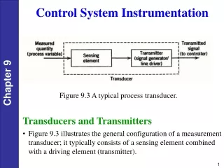
Transmitter outside the vessel High and low pressure capillaries DPT Low pressure tap with diaphragm seal High pressure tap with diaphragm seal Differential Pressure Capacitive transmitter with a seal • Standard differential pressure transmitter connected to the elbow with a diaphragm seal. • Through the seal the fill fluid transfers the process pressure from the seal to the measuring instrument hydraulically • Used in hot temperature or highly corrosive processes • Temperature limitation due to fill fluid (usually 400 ºC)
Differential Pressure Capacitive transmitter with a seal • Creative Engineers Inc • Fill fluid: Sodium-potassium alloy (NaK) or sodium • High temperature up to 815 ºC • It can be used with standard pressure transmitter • It can be used with diaphragms of any material • They proposed 316LNIG • They have supplied equipment for molten lead
Primary coolant: FlowExperimental techniques • CIRCE Venturi flow meter • Venturi flow meter manufactured by Euromesuri s.r.l. • Tested the ENEA Brasimone Research Centre • Tested with Lead Bismuth Eutectic (LBE) • The experimental calibration of the Venturi-Nozzle flow meter allowed qualifying the instrument giving an accurate correlation curve. • KArlsruhe Lead LAboratory (KALLA). Germany • Natec Schultheiß turbine flow meter installed in the THESYS loop • Tested with Lead Bismuth Eutectic (LBE) • Bearing had problems to withstand corrosion