Download
1 / 62
660 likes | 933 Views
Chapter 31. Faraday’s Law. Ampere’s law. Magnetic field is produced by time variation of electric field. Induction. A loop of wire is connected to a sensitive ammeter When a magnet is moved toward the loop, the ammeter deflects. Induction.

E N D
Chapter 31 Faraday’s Law
Ampere’s law • Magnetic field is produced by time variation of electric field
Induction • A loop of wire is connected to a sensitive ammeter • When a magnet is moved toward the loop, the ammeter deflects
Induction • An induced current is produced by a changing magnetic field • There is an induced emf associated with the induced current • A current can be produced without a battery present in the circuit • Faraday’s law of induction describes the induced emf
Induction • When the magnet is held stationary, there is no deflection of the ammeter • Therefore, there is no induced current • Even though the magnet is in the loop
Induction • The magnet is moved away from the loop • The ammeter deflects in the opposite direction
Induction • The ammeter deflects when the magnet ismoving toward or awayfrom the loop • The ammeter also deflects when the loop is moved toward or away from the magnet • Therefore, the loop detects that the magnet is moving relative to it • We relate this detection to a change in the magnetic field • This is the induced current that is produced by an induced emf
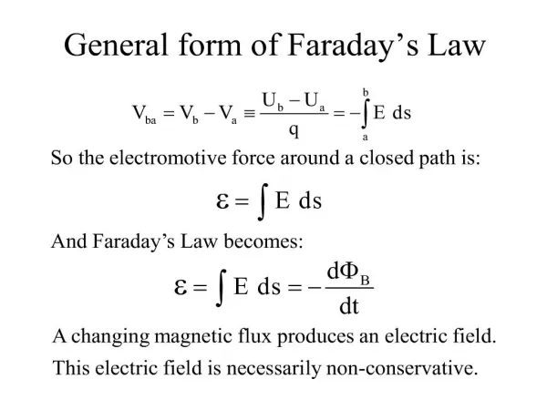
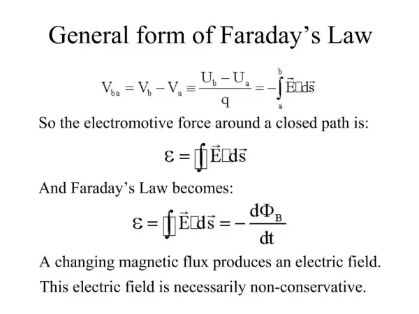
Faraday’s law • Faraday’s law of induction states that “the emf induced in a circuit is directly proportional to the time rate of change of the magnetic flux through the circuit” • Mathematically,
Faraday’s law • Assume a loop enclosing an area A lies in a uniform magnetic field B • The magnetic flux through the loop is FB = BA cos q • The induced emf is • Ways of inducing emf: • The magnitude of B can change with time • The area A enclosed by the loop can change with time • The angle q can change with time • Any combination of the above can occur
Motional emf • A motional emf is one induced in a conductor moving through a constant magnetic field • The electrons in the conductor experience a force, FB = qv x B that is directed along ℓ
Motional emf • FB = qv x B • Under the influence of the force, the electrons move to the lower end of the conductor and accumulate there • As a result, an electric field E is produced inside the conductor • The charges accumulate at both ends of the conductor until they are in equilibrium with regard to the electric and magnetic forces • qE = qvB or E = vB
Motional emf • E = vB • A potential difference is maintained between the ends of the conductor as long as the conductor continues to move through the uniform magnetic field • If the direction of the motion is reversed, the polarity of the potential difference is also reversed
Example: Sliding Conducting Bar • The induced emf is
Lenz’s law • Faraday’s law indicates that the induced emf and the change in flux have opposite algebraic signs • This has a physical interpretation that has come to be known as Lenz’s law • Lenz’s law: the induced current in a loop is in the direction that creates a magnetic field that opposes the change in magnetic flux through the area enclosed by the loop • The induced current tends to keep the original magnetic flux through the circuit from changing
Lenz’s law • Lenz’s law: the induced current in a loop is in the direction that creates a magnetic field that opposes the change in magnetic flux through the area enclosed by the loop • The induced current tends to keep the original magnetic flux through the circuit from changing B is increasing with time B is decreasing with time
Electric and Magnetic Fields • Ampere-Maxwell law • Faraday’s law
Example 1 .A long solenoid has nturns per meter and carries a current Inside the solenoid and coaxial with it is a coil that has a radius R and consists of a total of Nturns of fine wire. What emf is induced in the coil by the changing current?
Example 2 A single-turn, circular loop of radius R is coaxial with a long solenoid of radius r and length ℓ and having Nturns. The variable resistor is changed so that the solenoid current decreases linearly from I1 to I2in an interval Δt. Find the induced emf in the loop.
Example 3 A square coil (20.0 cm × 20.0 cm) that consists of 100 turns of wire rotates about a vertical axis at 1 500 rev/min. The horizontal component of the Earth’s magnetic field at the location of the coil is 2.00 × 10⁻⁵ T. Calculate the maximum emf induced in the coil by this field.
Chapter 32 Induction
Self-Inductance • When the switch is closed, the current does not immediately reach its maximum value • Faraday’s law can be used to describe the effect • As the current increases with time, the magnetic flux through the circuit loop due to this current also increases with time • This corresponding flux due to this current also increases • This increasing flux creates an induced emf in the circuit
Self-Inductance • Lenz Law: The direction of the induced emf is such that it would cause an induced current in the loop which would establish a magnetic field opposing the change in the original magnetic field • The direction of the induced emf is opposite the direction of the emf of the battery • This results in a gradual increase in the current to its final equilibrium value • This effect is called self-inductance • The emf εL is called a self-induced emf
Self-Inductance: Coil Example • A current in the coil produces a magnetic field directed toward the left • If the current increases, the increasing flux creates an induced emf of the polarity shown in (b) • The polarity of the induced emf reverses if the current decreases
Solenoid • Assume a uniformly wound solenoid having N turns and length ℓ • The interior magnetic field is • The magnetic flux through each turn is • The magnetic flux through all N turns • If I depends on time then self-induced emf can found from the Faraday’s law
Solenoid • The magnetic flux through all N turns • Self-induced emf:
Inductance • L is a constant of proportionality called the inductance of the coil and it depends on the geometry of the coil and other physical characteristics • The SI unit of inductance is the henry (H) • Named for Joseph Henry
Inductor • A circuit element that has a large self-inductance is called an inductor • The circuit symbol is • We assume the self-inductance of the rest of the circuit is negligible compared to the inductor • However, even without a coil, a circuit will have some self-inductance Flux through solenoid Flux through the loop
The effect of Inductor • The inductance results in a back emf • Therefore, the inductor in a circuit opposes changes in current in that circuit
RL circuit • An RL circuit contains an inductor and a resistor • When the switch is closed (at time t = 0), the current begins to increase • At the same time, a back emf is induced in the inductor that opposes the original increasing current
RL circuit • Kirchhoff’s loop rule: • Solution of this equation: where - time constant
Chapter 32 Energy Density of Magnetic Field
Energy of Magnetic Field • Let U denote the energy stored in the inductor at any time • The rate at which the energy is stored is • To find the total energy, integrate and
Energy of a Magnetic Field • Given U = ½L I 2 • For Solenoid: • Since Aℓ is the volume of the solenoid, the magnetic energy density, uB is • This applies to any region in which a magnetic field exists (not just the solenoid)
Chapter 32 LC Circuit
LC Circuit • A capacitor is connected to an inductor in an LC circuit • Assume the capacitor is initially charged and then the switch is closed • Assume no resistance and no energy losses to radiation
LC Circuit • With zero resistance, no energy is transformed into internal energy • The capacitor is fully charged • The energy U in the circuit is stored in the electric field of the capacitor • The energy is equal to Q2max / 2C • The current in the circuit is zero • No energy is stored in the inductor • The switch is closed
LC Circuit • The current is equal to the rate at which the charge changes on the capacitor • As the capacitor discharges, the energy stored in the electric field decreases • Since there is now a current, some energy is stored in the magnetic field of the inductor • Energy is transferred from the electric field to the magnetic field
LC circuit • The capacitor becomes fully discharged • It stores no energy • All of the energy is stored in the magnetic field of the inductor • The current reaches its maximum value • The current now decreases in magnitude, recharging the capacitor with its plates having opposite their initial polarity
LC circuit • Eventually the capacitor becomes fully charged and the cycle repeats • The energy continues to oscillate between the inductor and the capacitor • The total energy stored in the LC circuit remains constant in time and equals
LC circuit Solution: It is the natural frequency of oscillation of the circuit
LC circuit • The current can be expressed as a function of time • The total energy can be expressed as a function of time
LC circuit • The charge on the capacitor oscillates between Qmax and -Qmax • The current in the inductor oscillates between Imax and -Imax • Q and I are 90o out of phase with each other • So when Q is a maximum, I is zero, etc.
LC circuit • The energy continually oscillates between the energy stored in the electric and magnetic fields • When the total energy is stored in one field, the energy stored in the other field is zero
LC circuit • In actual circuits, there is always some resistance • Therefore, there is some energy transformed to internal energy • Radiation is also inevitable in this type of circuit • The total energy in the circuit continuously decreases as a result of these processes
Problem 2 A capacitor in a series LC circuit has an initial charge Qmax and is being discharged. Find, in terms of L and C, the flux through each of the N turns in the coil, when the charge on the capacitor is Qmax /2. The total energy is conserved:
Chapter 31 Maxwell’s Equations