Download

1 / 45
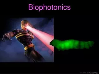
470 likes | 828 Views
Biophotonics lecture 16. November 2011. Magnification and resolution: the Abbe limit. f. f. f. f. a. a ’. Fourier plane. Image. Point object. Magnification : m=1 Angles : sin( a ’)=sin( a) a ’= a. Magnification and resolution: the Abbe limit. f. f. 2f. 2f. a. a ”.

E N D
Magnification and resolution: the Abbe limit f f f f a a’ Fourierplane Image Point object Magnification: m=1 Angles: sin(a’)=sin(a) a’=a
Magnification and resolution: the Abbe limit f f 2f 2f a a” Fourierplane Image Point object Magnification: m=2 Angles: sin(a’)=sin(a) /2 a’<a
Magnification and resolution: the Abbe limit f f f f a a’ Fourierplane Image Point object Magnification: m Angles: sin(a’)=sin(a) /m Smallestdistance (image): d’ = l/ (2 sin(a’)) = m l/ (2 sin(a)) Smallestdistance(sample):d = l/ (2 sin(a))
Magnification and resolution: the Abbe limit NA=n sin a Abbe resolutionlimit: d=l/(2NA) http://biology.about.com
McCutchen generalised aperture 2pn/l Ewald sphere
Optical Transfer Function (OTF): For incoherent microscopy techniques, e.g. fluorescence microscopy Missing cone Axialsupport Lateral support
Today: • How to do optical sectioning and fill the missing cone. • How to increase the lateral support and break the Abbe-limit. • Fluorescence microscopy in general.
FluorescenceMicroscopy • advantages: • High contrast • High specificity • but: • Noopticalsectioning in wide-fieldmode
Excitation, e.g. with 488nm Vibrational relaxation Emission, e.g. with 525nm Vibrational relaxation Energy
Absorption Emission Abbyad et al., PNAS December 18, 2007 vol. 104 no. 51 20189-20194
Camera High contrast: Excitation, e.g. with 488nm Tube lens Emission, e.g. with 525nm Blue light source Dichromatic reflector reflects blue light transmits green light Objective Sample fluorescence
Fluorochromes • Fluorescence microscopy differentiates between two kinds of fluorochromes: • Primary fluorescence (autofluorescence) • Secondary fluorescence (fluorochromation) • Fluorescence dyes • Immunofluorescence (using Antibodies) • Molecular tags (SNAP Tag, ...) • Fluorescent Proteins • Applications of fluorochromes • Identification of otherwise invisible structures • Localization and identification of otherwise invisible structures • Monitoring of physiological processes • Specific detection of a protein • Using photo-physical properties of dyes (e.g. switching) for super-resolution
Primary fluorescence (autofluorescence) • Most samples fluoresce when excited with short-wave light • Fluorescence very often occurs for systems containing many conjugated double bonds: • e.g. chlorophyll exhibits dark red fluorescence when excited by blue or red light Porphyrin ring – central unit in Chlorophyll Moss reeds – green excitation
http://en.wikipedia.org/wiki/File:Chlorophyll_ab_spectra2.PNGhttp://en.wikipedia.org/wiki/File:Chlorophyll_ab_spectra2.PNG
Further examples: • Riboflavine (550nm) • NAD(P)H (460nm, 400ps) • Elastin und Collagen (305-450nm) • Retinol (500nm) • Cuticula (blue) • Lignin (> 590nm) • DNA (Ex @320nm, 390nm) • Aminoacids: • Tryptophane (348nm, 2.6ns) • Tyrosin (303nm, 3.6ns, weak) • Phenylalanine (282nm weak) • Resins, Oils Eucalyptus leaf section – UV excitation http://en.wikipedia.org/wiki/Autofluorescence Nematode living sample – UV excitation
Secondary fluorescence (fluorochromation) • Staining (labeling) specific structures with fluorescent labels (dyes): fluorochromation • Small dye concentrations are sufficient due to high fluorescence contrast fluorescence labels are superior than bright field dyes • Single molecule sensitivity • Fluorescence labels must selectively bind to structures or selectively accumulate in specific compartments • e.g. DAPI (= 4',6-diamidino-2-phenylindole) to label DNA (cell nuclei) Fluorescence image of Endothelium cells. Microtubili are labeld in green, while actin filaments are labeled red. DNA within cell nuclei are stained with DAPI. DAPI: lexc = 358 nmlem = 461 nm some dyes unquench upon binding
Secondary fluorescence (fluorochromation): Immunofluorescence • Immunofluorescence (antibody staining) is the labeling of specific proteins with an antibody which is visualized by a dye • Antibodies are proteins which are used by the immune sys-tem to identify and neutralize foreign substances (antigens) • Antibodies are made of two large heavy chains (~440 amino acids) and two small light chains(~220 amino acids) • C-region is similar for all antibodies, while the V-regionis extremely variable and forms the specific binding sitefor the antigen i.e. every antibody can recognize andbind two antigens • Specificity: antibody-antigen reaction. The part of the antigen (protein) recognized by an antibody is called an epitope. Highly specific interaction, called induced fit, allows antibodies to identify and bind only their unique antigen in the midst of the millions of different molecules that make up an organism V C
Secondary fluorescence (fluorochromation): Immunofluorescence • Different groups of antibodies exist: • Polyclonal antibodiesThey are a mixture of antibodies secreted against a specific antigen, each recognizing a different epitope i.e. bind to different areas of the protein. The protein (e.g. tubulin) for which a special antibody should be generated is injected into a suitable mammal (mostly rats, mice or goats).Antibodies against the protein are produced by the mammalian immune response and can be isolated from the blood serum • Monoclonal antibodiesare all identical and bind to the same epitope • Synthetic antibodiesare monoclonal antibodies which are produced in-vitro i.e. via microorganism • Other systemsscFv (M. Bruchez): single chain variable region anitbodiesnanobodies (H. Leohardt): small (from Camelidae) and not degrated quickly inside a cell
Secondary fluorescence (fluorochromation): Immunofluorescence • Direct immunofluorescence • For the direct or primary labeling the specific antibody for the investigated protein is labeled with the fluorochrome • The labeled antibodies are brought onto the sample and only bind specifically to the wanted protein (antigen = ligand); non bound antibodies are washed out • Detection of the bound antibodies via the attached fluorochrome Localization of the wanted protein An interphase female human fibroblast cell. Arrow points to the corresponding X chromosome (right). Labeling of a DNA-associated histone protein
Secondary fluorescence (fluorochromation): Immunofluorescence • Indirect immunofluorescence • Two sets of antibodies; Primary antibody detects antigen A subsequent, secondary (indirect), dye-coupled antibody recognizes the primary antibody. • Signal amplification (several secondaries bind to one primary) • Color palette separating staining from target • Example: • 1. Antibody / Rat – Anti TubulinAntibody against tubulin generated in a rat • 2. Antibody / Goat – Anti Ratfluorescently labeled antibody against all rat antibodies (generated in a goat) • Negative test: Primary antibody is left out in order to test if the fluorescence labeled secondary antibody binds unspecifically to the sample
Secondary fluorescence (fluorochromation): Immunofluorescence Indirect immunofluorescence • GPCR transfected HEK cells: • Double staining: • For an identification of single cells the dye Hoechst 33342 was employed (cell nuclei: blue); • Cell bound primary mouse anti-GPCR antibodies were detected by secondary goat anti-mouse Ig(H+L) antibodies labeled with Alexa Fluor 488 (GPCR-protein: green). • The fluorescence labeled secondary antibodies can be employed for all antibodies produced within one animal e.g. goat serum against rats reacts with all primary antibodies produced in rats
Secondary fluorescence (fluorochromation) Dye artefacts • Bleaching: Fluorescence dye is destroyed by irradiation with light • Quenching: Fluorescence can be quenched (reduced) for large dye concentrations • Cross-Talk: Cross-Excitation: Simultaneous excitation of two dyes if their excitation wavelengths are too close to each other Bleed through: In case the emission spectra overlap too much both dyes will be detected but to different amounts Can be compensated by calibration and an inverse matrix technique "Spectral unmixing"
FluorescenceMicroscopy Optical sectioning Missing cone
Confocal fluorescence microscopy • Reduction of out of focus light • A confocal microscope uses focused laser illumination and a pinhole in an optically conjugate plane in front of the detector to eliminate out-of-focus blur • As only light produced by fluorescence close to the focal plane is detected, the contrast is much better than that of wide-field microscopes. • Allows recording individual optical sections or three dimensional reconstruction of objects
Confocal fluorescence microscopy • Reduction of out of focus light • In contrast to widefiled fluorescence microscopy where the whole sample is illuminated in confocal microscopy only one point in the sample is illuminated at a time • 2D or 3D imaging requires scanning over a regular raster (i.e. a rectangular pattern of parallel scanning lines) in the specimen: raster-scan • Comparison widefiled vs. confocal Line-wise scanned image Cell in its meta-/ana-phase. Plasma membrane is stained with a red fluorescing antibody while the spindle apparatus is labeled with a green fluorescent marker
The confocal PSF: Beam scan scan position: s - The sample is a point source, fixed at position 0. - For each scan position s the illumination beam is moved to this position s, i.e. we illuminate with the shifted excitation PSF, hillu(r-s). The point source, at r=0, willbe illuminated with and emit fluorescence with an intensity proportional to - This emission light is imaged with the PSF h(r) of the optical system and forms an imagein the pinhole plane. - Light not falling on the pinhole is blocked. Because of the de-scanning, the pinhole movesalong with the scan position. , with := - The resulting light distribution is integrated on the PMT detector, yielding the finalconfocal PSF:
The confocal PSF: detectionPSF illuminationPSF Detection PSF: the smaller the pinhole, the finer the detection PSF BUT: light is lost, as also IN-FOCUS light is blocked Bad signal-to-noise For pointlike pinhole: detection PSF approaches
Confocal fluorescence microscopy Reduction of out of focus light Resolution in confocal microscopyComparison of axial (x-z) point spread functions for widefield (left) and confocal (right) microscopy
kx,y kx,y a kz kz Increasing the aperture angle (a) enhances resolution !! The confocal OTF: PSF(r) = PSFExcitation(r) PSFDetection(r) OTF(k) = OTFExcitation(r) OTFDetection(r) Missing conehas been filled !! Missing cone Lateral support hasbeen increased.
Wehavecircumventedthe Abbe-limit: Abbe Confocal
Wehavecircumventedthe Abbe-limit, BUT: in-plane, in-focus OTF1.4 NA Objective WF Limit 1 AU Almost no transfer 0.3 AU WF New Confocal Limit
Confocal laser scanning microscopy • In confocal laser scanning microscopy laser light is focused to a small point at the focal plane of the specimen and moved / scanned by a computer controlled scanning mirror in the X-Y direction at the focal plane. • The fluorescent emission is sent through a pinhole and recorded by a photon multiplier tube (PMT) • An image is assembled with the help of a computer • Advantages: • Good axial out-of focus suppression • Quantification of fluorescence intensity • Simultaneous recording of different dyes in different channels • Disadvantages: • High costs (why?) • Artifacts due to coherence of laser and laser fluctuations • High amount of photo-bleaching
Confocal laser scanning microscopy • Experimental Setup • Scanning andDescanningby same element
Confocal laser scanning microscopy • Scan Head: • Excitation filter / Wavelength selection • Scan-System • Beamsplitter • Pinhole • Detectors (photomultiplier) dichromaticbeamsplitters excitation filter AcoustoOpticTunable Filter (AOTF) Acousto-optic tunable filter (AOTF) for laser intensity control and wavelength selection in confocal microscopy.
Confocal laser scanning microscopy • Scan System: • Mirror system is used to scan laser beam line by line over the sample • Mirror system consists of two rotating mirrors; one for scanning the laser in x-direction and the other for movement in the y-direction • Beam separation • In confocal microscopy several wavelength bands can be detected in parallel. Beam splitting is performed by dichroitic mirrors + filters,prisms, diffraction gratings + apertures. DiffractionGrating variable apertures pinhole more detectors dichroitic beam splitter
Confocal laser scanning microscopy • Pinhole: • Pinhole in the optically conjugate sample plane in front of the detector to eliminate out-of-focus blur can be adjusted continuously in its size • Pinhole size determines how much out-of-focus light is eliminated and how much light reaches the detector • The smaller the pinhole the better the axial resolution the smaller the brightness • Pinhole diameter = 1 Airy disc:Pinhole diameter corresponds to diameter of dark ring • Size of this maximum depends on magnification of objective and wavelength of light • Pinhole diameter needs to be adjusted on experimental parameters • < 1 Airy Disc • Improved x,y,z-resolution • Signal losses • > 1 Airy Disc • Improved brightness • Partial loss of confocal effect
High dynamic range (Voltage can be adjusted) • Multiplicative noise • dark noise (cooling) • cosmic radiation • Confocal laser scanning microscopy • Photomultiplier: • As detectors photomultipliers (PMT) are used
Confocal laser scanning microscopy • Photomultiplier: • PMT collects and amplifies incoming photons / electrons and reacts quickly and sensitive on incoming lights • PMTs do not generate an image!Image is generated by a computerPMTs amplify brightness i.e. intensity of incoming light • PMTs see black and white!Wavelength of incoming light is irrelevant for PMTs In order to measure different wavelengths the light must be filtered and distributed onto several detectors. Every single detector displays the intensity of the selected wavelength area.
Confocal laser scanning microscopy • Modern detectors: • GAsP PMTs, high efficiency • avalanche photo diodes (APDs), extremely efficient, small area, low maximum rate • APD arrays (expensive) • APD/PMT Hybrid detectors
Wide-field vs. confocal Widefield Comparison of widefield (upper row) and laser scanning confocal fluorescence microscopy images (lower row). (a) and (b) Mouse brain hippocampus thick section treated with primary antibodies to glial fibrillary acidic protein (GFAP; red), neurofilaments H (green), and counterstained with Hoechst 33342 (blue) to highlight nuclei. (c) and (d) Thick section of rat smooth muscle stained with phalloidin conjugated to Alexa Fluor 568 (targeting actin; red), wheat germ agglutinin conjugated to Oregon Green 488 (glycoproteins; green), and counterstained with DRAQ5 (nuclei; blue). (e) and (f) Sunflower pollen grain tetrad autofluorescence. Mouse Brain Hippocampus Smooth Muscle Sunflower Pollen Grain Confocal