Semiconductor Materials
Semiconductor Materials. Department of Electronic and Electrical Engineering. Lecturers: Prof. Tatiana Perova, SNIAM building, perovat@tcd.ie OBJECTIVES: This course deals with an introduction to semiconductor materials. SYLLABUS:

Semiconductor Materials
E N D
Presentation Transcript
Department of Electronic and Electrical Engineering Lecturers: Prof. Tatiana Perova, SNIAM building, perovat@tcd.ie OBJECTIVES: This course deals with an introduction to semiconductor materials. SYLLABUS: Semiconductors: Intrinsic silicon, extrinsic n and p type silicon, mobility of carriers, carrier transport in semiconductors; p-n junctions.
Semiconductor Materials • The Semiconductor Industry • Semiconductor devices such as diodes, transistors and integrated circuits can be found everywhere in our daily lives, in Walkman, televisions, automobiles, washing machines and computers. We have come to rely on them and increasingly have come to expect higher performance at lower cost. • Personal computers clearly illustrate this trend. Anyone who wants to replace a three to five year old computer finds that the trade-in value of his (or her) computer is surprising low. On the bright side, one finds that the complexity and performance of the today’s personal computers vastly exceeds that of their old computer and that for about the same purchase price, adjusted for inflation. • While this economic reality reflects the massive growth of the industry, it is hard to even imagine a similar growth in any other industry. For instance, in the automobile industry, no one would even expect a five times faster car with a five times larger capacity at the same price when comparing to what was offered five years ago. Nevertheless, when it comes to personal computers, such expectations are very realistic. • The essential fact which has driven the successful growth of the computer industry is that through industrial skill and technological advances one manages to make smaller and smaller transistors. These devices deliver year after year better performance while consuming less power and because of their smaller size they can also be manufactured at a lower cost per device.
Introduction to Semiconductors Objective of the lecture: Define a semiconductor – no. of electrons in outer shell, location on periodic table, most commonly used ones etc. Know the crystal structure of silicon, the cause and result of defects. Understand intrinsic and extrinsic semiconductor behaviour, know how to affect this behaviour through doping. Explain in detail what depletion regions are and how they are formed. P-N junction
Why semiconductors? • SEMICONDUCTORS: They are here, there, and everywhere • Computers, palm pilots, Silicon (Si) MOSFETs, ICs, CMOS laptops, anything “intelligent” • Cell phones, pagers Si ICs, GaAs FETs, BJTs • CD players AlGaAs and InGaP laser diodes, Si photodiodes • TV remotes, mobile terminals Light emitting diodes (LEDs) • Satellite dishes InGaAs MMICs (Monolithic Microwave ICs) • Fiber networks InGaAsP laser diodes, pin photodiodes • Traffic signals, car GaN LEDs (green, blue) taillights InGaAsP LEDs (red, amber) • Air bags Si MEMs, Si ICs • and, they are important, especially to Elec.Eng.& Computer Sciences
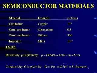
Introduction Semiconductors are materials whose electrical properties lie between Conductors and Insulators. Ex : Silicon and Germanium Give the examples of Conductors and Insulators! Difference in conductivity
Semiconductor Materials • Elemental semiconductors – Si and Ge (column IV of periodic table) –compose of single species of atoms • Compound semiconductors – combinations of atoms of column III and column V and some atoms from column II and VI. (combination of two atoms results in binary compounds) • There are also three-element (ternary) compounds (GaAsP) and four-elements (quaternary) compounds such as InGaAsP.
Semiconductor Materials • The wide variety of electronic and optical properties of these semiconductors provides the device engineer with great flexibility in the design of electronic and opto-electronic functions. • Ge was widely used in the early days of semiconductor development for transistors and diods. • Si is now used for the majority of rectifiers, transistors and integrated circuits. • Compounds are widely used in high-speed devices and devices requiring the emission or absorption of light. • The electronic and optical properties of semiconductors are strongly affected by impurities, which may be added in precisely controlled amounts (e.g. an impurity concentration of one part per million can change a sample of Si from a poor conductor to a good conductor of electric current). This process called doping.
Solid state structures A crystalline solid is distinguished by the fact that atoms making the crystal are arranged in a periodic fashion. That is, there is some basic arrangement of atoms that is repeated throughout the entire solid. Thus the crystal appears exactly the same at one point as it does at a series of other equivalent points, once the basic periodicity is discovered. However, not all solids are crystals (Fig. 2); some have no periodic structure at all (amorphous solids), and other are composed of many small regions of single-crystal material (polycrystalline solids). The periodic arrangement of atoms in crystal is called the lattice; the lattice contains a volume, called a unit cell, which is representative of the entire lattice and is regularly repeated throughout the crystal.
Solid state structures Unit cells for types of cubic lattice structure. • Cubic lattices: Diamond lattice unit cell, showing the four nearest neighbour structure The basic lattice structure for many important semiconductors is the diamond lattice, which is characteristic of Si and Ge. In many compound semiconductors, atoms are arranged in a basic diamond structure but are different on alternating sites. This is called a zincblende lattice and is typical of the III-V compounds. The diamond lattice can be thought of as an fcc structure with an extra atom placed at a/4+b/4+c/4 from each of the fcc atoms.
Solid state structures Each atom in the diamond lattice has a covalent bond with four adjacent atoms, which together form a tetrahedron. This lattice can also be formed from two fcc-cubic lattices, which are displaced along the body diagonal of the larger cube in Figure by one quarter of that body diagonal. The diamond lattice therefore is a fcc-cubic lattice with a basis containing two identical atoms. The diamond lattice of silicon and germanium. The zinc-blende crystal structure of GaAs and InP
Atoms and electrons We shall investigate some of the important properties of electrons, with special emphasis on two points: (1) the electronic structure of atoms and (2) the interaction of atoms and electrons with excitation, such as the absorption and emission of light. By studying electron energies in an atom, we lay the foundation for understanding the influence of the lattice on electrons participating in current flow through a solid. One of the most valuable experiments of modern physics is the analysis of absorption and emission of light by atoms. For example, an electric discharge can be created in a gas, so that the atoms begin to emit light with wavelengths characteristic of the gas. The result of emission spectra experiments led Niels Bohr to construct a model for the hydrogen atom, based on the mathematics of planetary systems. If the electron in the hydrogen atom has a series of planetary-type orbits available to it, it can be excited to an outer orbit and then can fall to any one of the inner orbits, giving off energy corresponding to one of the lines seen in a spectrum.
The Bohr model To develop the model, Bohr made several postulates: 1. Electrons exist in certain stable, circular orbits about the nucleus. 2. The electron may shift to an orbit of higher or lower energy, thereby gaining or losing energy equal to the difference in the energy levels (by absorption or emission of a photon of energy hν). However, the simple Bohr model, which accurately described the gross features of the hydrogen spectrum, did not include many fine features. These features were described later by principles of quantum mechanics.
The Silicon Atom Finally, the work of Bohr, Boltzmann, Plank, Einstein and others has developed an understanding of the atomic structure which shows that electrons circle the nucleus in orbits having different associated energies. The electrons also spin on their own axes. The energy of electrons is quantised in that only certain discrete levels of energy can be possessed by electrons and no values in between these discrete levels are allowed. The levels exist in groups which are referred to as shells and there are sub-shells (l) within main shells (n). Silicon, Si, is a group IV material having an atomic number of 14. Consequently it has 14 positively charged protons and 14 neutrons in its nucleus. It has 14 orbiting negatively charged electrons: 2 in a full K shell; 8 in a full L shell and 4 in a half-full M sub-shell. With a half full outer sub-shell the atom has an affinity for 4 additional electrons to try to complete the outer sub-shell. The Pauli’s Exclusion Principle states that no two electrons in an atom or molecule can share the exact same quantum specification. In practice, this means that no more than two electrons can share precisely the same orbit or energy level and the two must have opposite spins.
The Silicon Atom A covalent bond can be formed between two atoms which have only one electron in an outer orbit or energy level. In this case the individual electrons from the separate atoms at the same energy level orbit both atoms jointly as shown in figures. Both atoms essentially share the pair of electrons at the given energy level in the outer sub-shell, with the two electrons having opposite spins. This forms a bonding attraction between the two atoms which is not extremely strong but is nonetheless powerful and maintains a high degree of stability in the material. In the case of Silicon, each of the 4 outer electrons enters into a covalent bond with a neighbouring atom. A Covalent Bond Formed by the Sharing of Electrons in an Outer Energy Level
- - - - - - - - - - - - - - Si 14 The Silicon Atomic Structure Silicon: our primary example and focus Atomic no. 14 14 electrons in three shells: 2 ) 8 ) 4 i.e., 4 electrons in the outer "bonding" shell Silicon forms strong covalent bonds with 4 neighbors However, like all other elements it would prefer to have 8 electrons in its outer shell
n=3 n=3 n=2 n=2 n=1 n=1 Atom 1 Atom 2 n=3 n=3 n=3 n=2 n=2 n=2 n=1 n=1 n=1 Atom 1 Atom 2 Atom 1 + 2 Band theory of a solid • A solid is formed by bringing together isolated single atoms. • Consider the combination of two atoms. If the atoms are far apart there is no interaction between them and the energy levels are the same for each atom. The numbers of levels at a particular energy is simply doubled • If the atoms are close together the electron wave functions will overlap and the energy levels are shifted with respect to each other.
n=3 • A solid will have millions of atoms close together in a lattice so these energy levels will creates bands each separated by a gap. • Conductors: • If we have used up all the electrons available and a band is still only half filled, the solid is said to be a good conductor. The half filled band is known as the conduction band. • Insulators: • If, when we have used up all the electrons the highest band is full and the next one is empty with a large gap between the two bands, the material is said to be a good insulator. The highest filled band is known as the valence band while the empty next band is known as the conduction band. n=2 n=1 Conduction band, half filled with electrons Valence band, filled with electrons Empty conduction band Large energy gap Valence band, filled with electrons
Empty conduction band Small energy gap Valence bands, filled with electrons At zero Kelvin – no conduction Semiconductors: • Some materials have a filled valence band just like insulators but a small gap to the conduction band. • At zero Kelvin the material behave just like an insulator but at room temperature, it is possible for some electrons to acquire the energy to jump up to the conduction band. The electrons move easily through this conduction band under the application of an electric field. This is an intrinsic semiconductor. Conduction band, with some electrons So where are all these materials to be found in the periodic table ? Top valence band now missing some electrons At room temperature – some conduction
Brief introduction to Semiconductors (conductivity for Si depends on doping, Cu ~ 6E7 -1m-1)Think of a crystal matrix of silicon atoms (Si has 4 valence electrons).
Diamond lattice structure The diamond lattice can be thought of as an fcc structure with an extra atom placed at a/4+b/4+c/4 from each of the fcc atoms. Diamond lattice - http://en.wikipedia.org/wiki/File:Diamond_cubic_animation.gif
- - - - - - - - - - - - - - Si 14 The Silicon Atomic Structure Silicon : It’s a Group 4 element which means it has 4 electrons in outer shell However, like all other elements it would prefer to have 8 electrons in its outer shell
Bonding of Si atoms This results in the covalent bonding of Si atoms in the crystal matrix A Covalent Bond Formed by the Sharing of Electrons in an Outer Energy Level
n=3 n=3 n=2 n=2 n=1 n=1 Atom 1 Atom 2 Band Gap Energy Discrete energy levels for 2 atoms separated by a large distance. Note that the band gap energy, Eg for insulators is ~ 10 eV, while for metals it is close to 0 eV (1eV=1.6x10⁻¹⁹ J). Typical continuous band pictures at 0 K for different solid materials.
Electrons and Holes Si and Ge are tetravalent elements – each atom of Si (Ge) has 4 valence electrons in crystal matrix T=0 all electrons are bound incovalent bondsno carriers available for conduction. For T> 0 thermal fluctuations canbreak electrons free creatingelectron-hole pairsBoth can move throughout the latticeand therefore conduct current.
Electrons and Holes For T>0 some electrons in the valence band receive enough thermal energy to be excited across the band gap to the conduction band. The result is a material with some electrons in an otherwise empty conduction band and some unoccupied states in an otherwise filled valence band. An empty state in the valence band is referred to as a hole. If the conduction band electron and the hole are created by the excitation of a valence band electron to the conduction band, they are called an electron-hole pair (EHP). Electron-hole pairs in a semiconductor. The bottom of the conduction band denotes as Ec and the top of the valence band denotes as Ev.
- - - - - - - - - - - - - - - - - - - - - - - - - - - - - - - - - - - - - - - - - - - - - - - - - - - - - - - - - - - - - - - - - - - - - - - - - - - - - - - - - - - - Free electron Vacancy left by electron. Overall charge on silicon is zero this “hole” must be positive Si Si Si Si Si Si Si Si Si Si Si Si Si Si Si Si Si Si Si Si Si - - + + Shares electrons with 4 neighbouring atoms 8 electrons in outer shell Adding heat (even to room temperature) allows some bonds to break, and electrons can flow Silicon Lattice Structure At 0K, all electrons are tightly shared with neighbours no current flow
Intrinsic Material A perfect semiconductor crystal with no impurities or lattice defects is called an intrinsic semiconductor. At T>0 Electron-hole pairs are generated EHPs are the only charge carriers in intrinsic material At T=0 K – No charge carriers Valence band is filled with electrons Conduction band is empty Since electron and holes are created in pairs – the electron concentration in conduction band, n (electron/cm3) is equal to the concentration of holes in the valence band, p (holes/cm3). Each of these intrinsic carrier concentrations is denoted ni. Thus for intrinsic materials n=p=ni Electron-hole pairs in the covalent bonding model in the Si crystal.
Intrinsic Material • At a given temperature there is a certain concentration of electron-hole pairs ni. If a steady state carrier concentration is maintained, there must be recombinationof EHPs at the same rate at which they are generated. Recombination occurs when an electron in the conduction band makes a transition to an empty state (hole) in the valence band, thus annihilating the pair. If we denote the generation rate of EHPs as gi(EHP/cm3·s) and the recombination rate as ri, equilibrium requires that ri = gi • Each of these rates is temperature dependent. For example, gi(T) increases when the temperature is raised, and a new carrier concentration ni is established such that the higher recombination rate ri (T) just balances generation. At any temperature, we can predict that the rate of recombination of electrons and holes ri, is proportional to the equilibrium concentration of electrons n0and the concentration of holes p0: ri = rn0p0 = rni2= gi • The factor ris a constant of proportionality which depends on the particular mechanism by which recombination takes place.
Increasing conductivity by temperature As temperature increases, the number of free electrons and holes created increases exponentially. Therefore the conductivity of a semiconductor is influenced by temperature
Increasing conductivity • The conductivity of the semiconductor material increases when the temperature increases. • This is because the application of heat makes it possible for some electrons in the valence band to move to the conduction band. • Obviously the more heat applied the higher the number of electrons that can gain the required energy to make the conduction band transition and become available as charge carriers. • This is how temperature affects the carrier concentration. • Another way to increase the number of charge carriers is to add them in from an external source. • Doping or implant is the term given to a process whereby one element is injected with atoms of another element in order to change its properties. • Semiconductors (Si or Ge) are typically doped with elements such as Boron, Arsenic and Phosphorous to change and enhance their electrical properties.
Extrinsic Material By doping, a crystal can be altered so that it has a predominance of either electrons or holes. Thus there are two types of doped semiconductors, n-type (mostly electrons) and p-type (mostly holes). When a crystal is doped such that the equilibrium carrier concentrations n0and po are different from the intrinsic carrier concentration ni, the material is said to be extrinsic. When impurities or lattice defects are introduced, additional levels are created in the energy bands structure, usually within the band gap. Donor impurities (elements of group V): P, Sb, As Acceptor elements (group III): B, Al, Ga, In Total number of electrons III – Al – 13 IV – Si – 14 V - P - 15 The valence and conduction bands of silicon with additional impurity energy levels within the energy gap.
Extrinsic Material – donation of electrons An impurity from column V introduces an energy level very near the conduction band in Ge or Si. This level is filled with electrons at 0 K, and very little thermal energy is required to excite these electrons to the conduction band. Thus, at about 50-100 K nearly all of the electrons in the impurity level are "donated" to the conduction band. Such an impurity level is called a donor level, and the column V impurities in Ge or Si are called donor impurities. From figure we note that the material doped with donor impurities can have a considerable concentration of electrons in the conduction band, even when the temperature is too low for the intrinsic EHP concentration to be appreciable. Thus semiconductors doped with a significant number of donor atoms will have n0>>(ni,p0) at room temperature. This is n-type material. n-type material Donation of electrons from a donor level to the conduction band
Extrinsic Material – acceptance of electrons Atoms from column III (B,Al, Ga, and In) introduce impurity levels in Ge or Si near the valence band. These levels are empty of electrons at 0 K. At low temperatures, enough thermal energy is available to excite electrons from the valence band into the impurity level, leaving behind holes in the valence band. Since this type of impurity level "accepts" electrons from the valence band, it is called an acceptorlevel, and the column III impurities are acceptor impurities in Ge and Si. As figure indicates, doping with acceptor impurities can create a semiconductor with a hole concentration p0much greater than the conduction band electron concentration n0(this is p-type material). P-type material Acceptance of valence band electrons by an acceptor level, and the resulting creation of holes.
Donor and acceptors in covalent bonding model In the covalent bonding model, donor and acceptor atoms can be visualized as shown in the Figure. An Sb atom (column V) in the Si lattice has the four necessary valence electrons to complete the covalent bonds with the neighboring Si atoms, plus one extra electron. This fifth electron does not fit into the bonding structure of the lattice and is therefore loosely bound to the Sb atom. A small amount of thermal energy enables this extra electron to overcome its coulombic binding to the impurity atom and be donated to the lattice as a whole. Thus it is free to participate in current conduction. This process is a qualitative model of the excitation of electrons out of a donor level and into the conduction band. Similarly, the column III impurity Al has only three valence electrons to contribute to the covalent bonding, thereby leaving one bond incomplete. With a small amount of thermal energy, this incomplete bond can be transferred to other atoms as the bonding electrons exchange positions. Donor and acceptor atoms in the covalent bonding model of a Si crystal.
- - - - - - - - - - - - - - - - - - - - - - - - - - - - - - - - - - - - - - - - - - - - - - - - - - - - - - - - - - - - - - - - - - - - - - - - - - - - - - - - - - - - - - - - - - - - - - - - - - - Si Si Si Si Si Si Si Si Si Si Si Si As As Si Si Si Si Si Si Si Si As Si - - + + + - - - Increasing conductivity by doping + • Inject Arsenic into the crystal with an implant step. • Arsenic is Group5 element with 5 electrons in its outer shell, (one more than silicon). • This introduces extra electrons into the lattice which can be released through the application of heat and so produces and electron current • The result here is an N-type semiconductor (n for negative current carrier)
- - - - - - - - - - - - - - - - - - - - - - - - - - - - - - - - - - - - - - - - - - - - - - - - - - - - - - - - - - - - - - - - - - - - - - - - - - - - - - - - - - - - - - - - - - - - - - - - Si Si Si Si Si Si Si Si Si Si Si Si Si Si Si Si Si Si Si B B Si B Si - - + + + + + + + + Increasing conductivity by doping + • Inject Boron into the crystal with an implant step. • Boron is Group3 element is has 3 electrons in its outer shell (one less than silicon) • This introduces holes into the lattice which can be made mobile by applying heat. This gives us a hole current • The result is a P-type semiconductor (p for positive current carrier)
Calculation of binding energy We can calculate rather simply the approximate energy required to excite the fifth electron of a donor atom into the conduction band (the donor binding energy) based on the Bohr model results: where m n*is the effective mass typical of semiconductors ( m0 = 9.11x10⁻³¹ kg is the electronic rest mass), is a reduced Planck’s constant and where εris the relative dielectric constant of the semiconductor material and 0 = 8.85x10⁻¹² F/m is the permittivity of free space.
The Fermi level The following consideration are used in the development of this statistics: Electrons in solids obey Fermi - Dirac statistics: (4.6) • indistinguishability of the electrons, • electron wave nature, • the Pauli exclusion principle. where k is Boltzmann’s constant k=8.62ּ10-5 eV/K=1.3810-23 J/K. The function f(E) called the Fermi-Dirac distribution function gives the probability that an available energy state at E will be occupied by an electron at absolute temperature T. The quantity EF is called the Fermi level, and it represents an important quantity in the analysis of semiconductor behavior. For an energy E = EF the occupation probability is (4.7) This is the probability for electrons to occupy the Fermi level.
The Fermi – Dirac distribution function At T=0K f(E) has rectangular shape the denominator of the exponent is 1/(1+0)=1 when (E<Ef), exp. negative 1/(1+)-0 when (E>Ef), exp. positive At 0 К every available energy state up to EF is filled with electrons, and all states above EF are empty. At temperatures higher than 0 K, some probability f(E) exists for states above the Fermi level to be filled with electrons and there is a corresponding probability [1 - f(E)] that states below EF are empty. The Fermi function is symmetrical about EF for all temperatures. The probability exists for state E above EF is filled – f(EF+ E) state Ebelow EFis filled – [1- f(EF - E)] The Fermi – Dirac distribution function for different temperatures The symmetry of the distribution of empty and filled states about EF makes the Fermi level a natural reference point in calculations of electron and hole concentrations in semiconductors. In applying the Fermi-Dirac distribution to semiconductors, we must recall that f(E) is the probability of occupancy of an available state at E. Thus if there is no available state at E (e.g., in the band gap of a semiconductor), there is no possibility of finding an electron there.
Relation between f(E) and the band structure Electron probability tail f(E) Hole probability tail [1-f(E)] In intrinsic material the Fermi level EF must lie at the middle of the band gap. In n-type material the distribution function f(E) must lie above its intrinsic position on the energy scale. The energy difference (Ec – EF) gives a measure of n. For p-type material the Fermi level lies near the valence band such that the [1-f(E)] tail below Ev is larger than the f(E) tail above Ec. The value of (EF – Ev) indicates how strongly p-type the material is. The distribution function has values within the band gap between Eν and Ec, but there are no energy states available, and no electron occupancy results from f(E) in this range.
Electron and Hole Concentrations at Equilibrium The Fermi distribution function can be used to calculate the concentrations of electrons and holes in a semiconductorif the densities of available states in the valence and conduction bands are known. The concentration of electrons in the conduction band is (4.8) where N(E)dE is the density of states (cm-3) in the energy range dE. The subscript 0 used for the electron and hole concentration symbols (n0, p0) indicates equilibrium conditions. The number of electrons per unit volume in the energy range dE is the product of the density of states and the probability of occupancy f(E).Thus the total electron concentration is the integral over the entire conduction band. The function N(E) can be calculated by using quantum mechanics and the Pauli exclusion principle. N(E) is proportional to E1/2, so the density of states in the conduction band increases with electron energy. On the other hand, the Fermi function becomes extremely small for large energies. The result is that the product f(E)N(E) decreases rapidly above Ec, and very few electrons occupy energy states far above the conduction band edge. Similarly, the probability of finding an empty state (hole) in the valence band [1 - f(E)] decreases rapidly below Ev, and most holes occupy states near the top of the valence band.
Band diagram, density of states, Fermi-Dirac distribution, and the carrier concentrations at thermal equilibrium Intrinsic semiconductor n-type semiconductor p-type semiconductor
The conduction band electron concentration is simply the effective density of states at Ec times the probability of occupancy at Ec: (4-9) In this expression we assume the Fermi level EF lies at least several kT below the conduction band. Then the exponential term is large compared with unity, and the Fermi function f(Ec) can be simplified as (4-10) Since kT at room temperature is only 0.026 eV, this is generally a good approximation. For this condition the concentration of electrons in the conduction band is (4-11) It can be shown that the effective density of states Nc is (4-12) Values of Nc can be tabulated as a function of temperature. As Eq. (4-11) indicates, the electron concentration increases as EF moves closer to the conduction band. By similar arguments, the concentration of holes in the valence band is (4-13) where Nvis the effective density of states in the valence band.
, The probability of finding an empty state at Ev, is (4-14) for EF larger than Ev by several kT. From these equations, the concentration of holes in the valence band is (4-15) The effective density of states in the valence band reduced to the band edge is (4-16) Eq. (4-15) predicts that the hole concentration increases as EF moves closer to the valence band. The electron and hole concentrations predicted by Eqs. (4-11) and (4-15) are valid whether the material is intrinsic or doped, provided thermal equilibrium is maintained. Thus for intrinsic material, EF lies at some intrinsic level Ei near the middle of the band gap, and the intrinsic electron and hole concentrations are (4-17)