Download
1 / 28
290 likes | 327 Views
Learn about the design concept for an 18MW ILC beam dump, including mechanical parameters, FLUKA and FLUENT studies. Explore the global effort outline for efficient design.

E N D
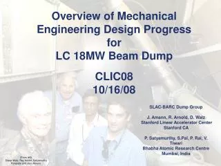
Status Update18MW ILC Beam Dump Design John Amann Mechanical Engineer SLAC National Accelerator Laboratory LC Beam Delivery Systems Global Design Effort
Outline • Introduction. • Mechanical Design Concept. • Beam Parameters used for FLUKA studies. • FLUKA studies. • FLUENT studies (conjugate heat transfer). • Summary. Global Design Effort
Introduction ILC Beam Dump Design Team • SLAC National Accelerator Laboratory: J. Amann, R. Arnold, D. Walz, A. Seryi • Bhabha Atomic Research Centre: P. Satyamurthy, P. Rai, V. Tiwari, K. Kulkarni Starting Point for Work • SLAC 2.2 MW Water Dump, The Stanford Two-Mile Accelerator, • R.B. Neal Ed, (1968). • High Power Water Beam Dump for a LC, M. Schmitz, • TESLA Collaboration Meeting, 16 Sept 2003. • ILC Main Beam Dumps -- Concept of a Water Dump, • D. Walz Snowmass, 18 Aug 2005. • Dumps and Collimators, ILC Reference Design Report, 2007 • T. Davenne, O. Caretta, C. Densham and R. Appleby, Pressure Transients in the ILC Beam Dump, LC-ABD Collaboration meeting, Birmingham University, 17 April 2008 Global Design Effort
Introduction The task force team studied the various aspects of the SLAC’s 2.2MW water beam dump and used it as the starting basic reference design for an ILC Beam dump, since it has all features required of an ILC beam dump (but at a lower power level) but proven design. This includes the use of a vortex-like flow pattern to dissipate and remove the energy deposited by the beam, the beam dump entrance window and its special cooling method, a remote window exchange mechanism, a hydrogen re-combiner, handling of radioactive 7Be, a tail catcher to attenuate the residual beam energy remaining after the vortex flow region, as well as related primary and secondary cooling loops. Global Design Effort
Mechanical Design Concept • The 18MW LC beam dump mechanical design is driven by parameters and constraints developed from FLUKA simulations, CFD thermal hydraulic simulations and analytic calculations. • The existing 2.2MW SLAC beam dump provides a baseline mechanical design to consider features which might be incorporated into the 18MW beam dump mechanical design concept. • The first step in creating a mechanical design concept for the beam dump is to establish the basic mechanical design parameters of the beam dump vessel and thin window. • The beam dump is a pressurized vessel containing heated and radioactive water and consequently for operation within the USA, must conform to the design and safety standards of the American Society of Mechanical Engineers Boiler and Pressure Vessel Code. Global Design Effort
Mechanical Design Concept Table of Beam Dump Design Parameters and Constraints Global Design Effort
Mechanical Design Concept Vessel Shell Inlet Headers Window Cooling Nozzle Supply Pipe Thin Window Outlet Header Flat Heads Global Design Effort
Mechanical Design Concept • Mechanical Design Parameters • (ASME BPVC Div. VIII) • Vessel Material – 316LN • Minimum Shell Thickness – 21mm • Minimum Flat Head Thickness – 70mm • Window Material – Ti-6Al-4V • Max. Design Pressure, 1mm Thick • Hemispherical Window – 32bar or 464psi Global Design Effort
Mechanical Design Concept Window Cooling Nozzle Thin Window Global Design Effort
Mechanical Design Concept Global Design Effort
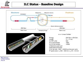
Beam Parameters The following beam parameters have been taken as reference for designing the beam dump: Electron/Positron energy: 500 GeV Number of electrons/positrons per bunch: 2x10¹⁰ Number of bunches per train: 2820 Duration of the bunch train: 0.95 ms Beam size: σx = 2.42mm σy= 0.27 mm Energy in one bunch train: 4.5 MJ Number of bunch trains per second: 4 Beam power: 18 MW Beam sweep radius: 6 cm Global Design Effort
Energy Density Modulation Around Sweep Path FLUKA Studies Global Design Effort
FLUKA Studies Global Design Effort
FLUKA Studies Energy deposited by one bunch train in the water (beam travelling along z-axis) max @ z=1.8m Radially integrated longitudinal linear power density max @ z=2.9m Global Design Effort
FLUKA Studies Longitudinal Power Density in Vessel Wall (20mm thick 316L SS) Beam @ r=45cm Beam @ r=35cm Global Design Effort
FLUKA Studies Heat Flux – Down Beam Head Global Design Effort
FLUKA Studies • A FLUKA analysis was carried out to • determine the beam power distribution • in the thin window. • The total power deposited is ~25 W • with a maximum power density of • 21W/cm3. • Functional fitted data is the • input for the CFD analysis. W/cm3 Global Design Effort
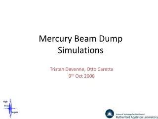
FLUENT Studies Total mass flow rate of water taken was 154kg/s. Water inlet was assumed to be at 500C as dictated by the primary coolant loop. The bulk outlet temperatures would be 780C for 18 MW average beam power. The water inlet velocity at the slit exit is 2.17 m/s. Velocity contours at z = 2.9m Steady state temperature distribution at z = 2.9m (Max average temperature : 1270C ) Global Design Effort
FLUENT Studies Maximum temperature variation as a function of time at z = 2.9m Maximum temperature variation as a function of time at z = 1.8 m Maximum temperature ~1550C and variation with time ~300C Maximum temperature ~1350C and variation with time ~360C Global Design Effort
FLUENT Studies Variation of inlet velocity at inlet exit along length of header. Global Design Effort
FLUENT Studies Temperature distribution in the vessel at z = 2.9m for the 0.45m radial beam location Temperature distribution in the vessel at z = 4.2m for the 0.45m radial beam location max vessel temperature - 940C min vessel temperature - 810C max vessel temperature - 900 C min vessel temperature - 700C Global Design Effort
FLUENT Studies Window Cooling - Work In Progress Global Design Effort
FLUENT Studies Window Cooling - Work In Progress Global Design Effort
FLUENT Studies Flat Head Cooling - Work In Progress Global Design Effort
FLUENT Studies Flat Head Cooling - Work In Progress Global Design Effort
FLUKA Studies Preliminary Activation Studies – First Design Concept Global Design Effort
Summary • Mechanical design concept under development. • Basic mechanical parameters established. • Window sealing design and remote exchange system still needs work. • Preliminary process design complete. • FLUKA and FLUENT studies nearly complete. • Beam dump parameters determined by physics. • Inlet headers, outlet header, and window locations optimized. • Working to finalize window cooling and down beam head cooling. • Shielding design and overall system integration still needs work. • Future work we feel is critical. • Build a scaled down version of beam dump to verify FLUENT studies. • Beam damage testing of thin window materials. Global Design Effort
Bonus Slides Variation of inlet velocity at inlet exit along length of header. Global Design Effort