Download
1 / 23
230 likes | 362 Views
R & D for particle accelerators in the CLF. Peter A Norreys Central Laser Facility STFC Fellow Visiting Professor, Imperial College London. Brief introduction to laser wakefield accelerators ASTRA laser Dream beam Photon acceleration ASTRA GEMINI laser specifications first results

E N D
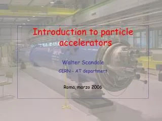
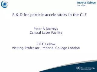
R & D for particle accelerators in the CLF Peter A Norreys Central Laser Facility STFC Fellow Visiting Professor, Imperial College London
Brief introduction to laser wakefield accelerators ASTRA laser Dream beam Photon acceleration ASTRA GEMINI laser specifications first results electron beam control for FEL’s VULCAN 10 PW laser specifications bunch charge betatron emission
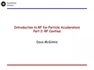
diffraction gratings Laser characteristics • 1PW = 1015 W • Power = Energy = 500 J = 11015 W • pulse duration 500 fs • To maximise the intensity on target, the beam must be focused to a small spot. • The focal spot diameter is 7 mm and is focused with an f/3.1 off-axis parabolic mirror • Intensity = Power = 1 x 10²¹ W cm-2 • Focused area Amplifier
Electron motion in an intense laser field • A single electron in an intense infinite plane polarised laser field exhibits a figure of eight motion due to the vxB term in the Lorentz force F = -e(E+vxB) • At relativistic intensities, electrons are accelerated in the direction of the propagation direction k twice every laser cycle. • The kinetic energy the electron acquires is roughly proportional to the ponderomotive potential energy Up Intensity on target 1016 Wcm-2 1018 Wcm-2 1021 Wcm-2 Up 1 keV 0.4 MeV 14 MeV
Laser wakefield acceleration • Perturbing ‘object’ passes through a medium which is displaced from equilibrium • The medium then returns creating oscillations • Areas of high and low electron density create extreme electric fields High intensity laser pulse Electron density Gas Jet
Electron acceleration Plasma electrons are trapped and accelerated by the laser’s wakefield Laser pulse Wakefield Electron injection Projection of electron density Collaboration between Oxford, RAL, IST Lisbon, University of Strathclyde, UCLA, and Imperial College London
Astra laser Single Beam Titanium Sapphire laser system 10 TW optical pulse at 10Hz / 25TW at 1Hz Operated to 2 target areas Experiments in Laser-Plasma Physics
Advantages of laser wakefield accelerators • Laser Plasma Accelerators have 10,000 higher electric field than conventional accelerators • Implies kilometer’s to centimeters reduction in size for same electron energy - attractive • Until 2004, they had produced broad range of energies which severely limited applications • Quasi mono-energetic electrons up to 100 MeVwere produced for the first time at RAL • Capilliary discharge experiments later extended this to 1 GeV at LBNL and 200 MeV at RAL. Astra Target Area 2 IC / RAL / Strathclyde / UCLA collaboration S.P.D.Mangles et al Nature, 431 , 535 (2004)
Photon acceleration Photon bunching in a wakefield Initial photon distribution Final photon distribution Photon frequency (rad/s) Scaled electron density Wakefield x – ct (m) Image taken from simulations using a dedicated wave-kinetic code
Modulational instability Modulation of a laser spectrum by itsown wakefield in a long (180 fs) -pulse experiment • 20 nm overall shift: ionisationblueshift • 5 nm peak separation: photon acceleration • Stokes separation would have been: • 30-40 nm
Theory and simulations • Analytic theory predicts additional peak splitting on top of Stokes splitting with 3-5 nm separation wakefield amplitude broadening of fundamental peak Simulations for 5, 10, 20, 40 bar backing pressure do not show peak splitting, but do show widening of the fundamental peak with wakefield amplitude and background density
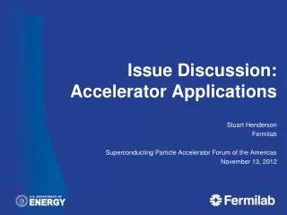
Ian Pearson, MP Minister of State for Science and Innovation , Dec 2007 Astra-Gemini facility Dual Beam Petawatt Upgrade of Astra (factor 40 power upgrade) 1022 W/cm2 on target irradiation 1 shot every 20 seconds Opened by the UK Science Minister (Ian Pearson MP) Dec 07 Significantly over-subscribed. Assessing need for 2nd target area.
SPECTRUM TIME SPECTRUM TIME 34 nm 40 fs Gemini Target Chamber • South Beamline of Gemini has been commissioned • Achieved target energy, spot size and almost pulse duration • Pulse duration ~ 45 fs (TBP 0.35)
Gemini First User Experiment • 10 weeks of user access to Gemini Target Area successfully completed • Imperial College Electron acceleration experiment • Systems are generally working well
Rapid Progress Subsequent work by IC team has shown that with good control of laser parameters, reproducibility can be obtained. Improved Laser Quality Unoptimised laser beam Effect of laser contrast ratio on electron beam stability in laser wakefield acceleration experiments S P D Mangles, A G R Thomas, et al., PLASMA PHYSICS AND CONTROLLED FUSION 48 (12B): B83-B90 Sp. Iss. SI, DEC 2006
Taylored density gradients produce small energy spread bunches • 10 TW beam focused on far edge of gas jet • Bunches of 0.76 +/- 0.02 MeV generated • Simulations indicate beams with 0.2 MeV energy spread with GeV energy and beyond may be possible
Vulcan facility 8 Beam CPA Laser 3 Target Areas 3 kJ Energy 1 PW Power Increased complexity, accuracy & rep-rate
TAP View of the lower floor New 10PW Target Area TAW New 10 PW Area TAW ‘New’ Target Area • 4m diameter chamber, 2.5m high • Short F, 45 degree optic to maximise space • Long F optic possible on N-S axis - affects final beam positioning.
Revolutionary bunch charge Taken to the 10PW level, 3D PIC simulations show that this can accelerate 2-40nC of charge. • 40nC at 1GeV • 14nC at 4 GeV • 2nC at 10GeV This is beyond Conventional Accelerators < 1nC Images courtesy of L.Silva
Betatron radiation • A 12 GeV beam with 1 nC charge will emit intense betatron radiation while accelerated while only losing 0.2% of its energy Images courtesy of L.Silva