Download
1 / 38
381 likes | 533 Views
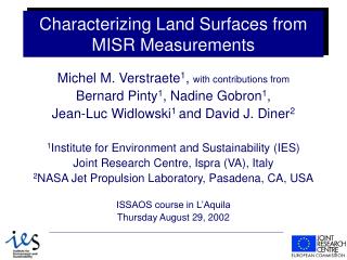
Characterizing Land Surfaces from MISR Measurements. Michel M. Verstraete 1 , with contributions from Bernard Pinty 1 , Nadine Gobron 1 , Jean-Luc Widlowski 1 and David J. Diner 2 1 Institute for Environment and Sustainability (IES) Joint Research Centre, Ispra (VA), Italy

E N D
Characterizing Land Surfaces from MISR Measurements Michel M. Verstraete1, with contributions from Bernard Pinty1, Nadine Gobron1, Jean-Luc Widlowski1 and David J. Diner2 1Institute for Environment and Sustainability (IES) Joint Research Centre, Ispra (VA), Italy 2NASA Jet Propulsion Laboratory, Pasadena, CA, USA ISSAOS course in L’Aquila Thursday August 29, 2002
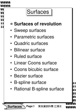
Outline • MISR and multiangular ToA observations • Surface anisotropy primer • Multiangular reflectance nomenclature • Interlude: The RPV GUI tool • MISR standard surface products • MISR non-standard surface products • Case study: AirMISR and surface heterogeneity
Overview of MISR • 9 cameras at ±70.5, ±60, ±45.6, ±26.1, 0° • Each camera at 446, 558, 672, and 866 nm • Spatial resolution: 275 m (250 m nadir) • Global mode: Full res. nadir and red, 1.1 km otherwise • Local mode: Full resolution all cameras and all bands • Swath: 360 km • Coverage: global (9 days) Ref: http://www-misr.jpl.nasa.gov/mission/minst.html
Multiangle animation Emigrant Gap Fire, California 13 August 2001 79 km Credit: NASA/GSFC/LaRC/JPL MISR Team
ToA anisotropy from MISR (1) Aerosols Clouds Vegetated land Shikoku Island, Japan April 13, 2001 RGB = R, G, B (26a) RGB = R, G, B (60f) 285 km Ref: http://www-misr.jpl.nasa.gov/gallery/galhistory/2001_may_02.html
ToA anisotropy (2) over Zambia, Namibia and Botswana 25 August 2000 Nadir Blue Nadir Green Nadir Red Nadir Green Nadir Red Nadir NIR 70º Aft Red (forward scatter) 70º Fwd Red (backscatter) Nadir Red Credit: NASA/JPL MISR Team
ToA anisotropy from MISR (3) Saskatchewan and Manitoba N April 17, 2001 Snow Forests Agriculture Roads RGB = Nir, R, G RGB = R60a, Rn, R60f 285 km Ref: http://www-misr.jpl.nasa.gov/gallery/galhistory/2001_may_30.html
ToA anisotropy from MISR (4) Lake Okeechobee N Farmland Everglades National Park Gulf of Mexico RGB = R, G, B RGB = R46a, Rn, R46f 191 km South Florida January 16, 2002 Ref: http://www-misr.jpl.nasa.gov/gallery/galhistory/2002_apr_17.html
Differentiating surface vegetation via angular signatures Gulf coast wetlands along the Pascagoula, Mobile-Tensaw, and Escambia Rivers are spectrally similar to surrounding vegetation but have a distinctive angular signature. nadir true color nadir near-infrared false color multi-angle false color fwd scatter, nadir, backscatter Mississippi, Alabama, FL 15 October 2001 Credit: NASA/JPL MISR Team
An anisotropy primer (1) • Solar illumination is highly directional, especially under clear skies • All surfaces, natural or artificial, and in particular water, soils, vegetation, snow and ice, are anisotropic • Surface anisotropy is controlled by the structure and optical properties of the observed media • Reflectance of geophysical media is bidirectional • Specular reflectance and hot spot, Lambertian panel • Atmospheric constituents also interact anisotropically with the radiation fields (Rayleigh, Mie scattering) • Anisotropy is itself a spectrally-dependent property
An anisotropy primer (2) • Imaging instruments with a small IFOV sample the reflectance of the surface-atmosphere system in the direction of the sensor, measure the hemispherical-conical reflectance of the geophysical system • These measurements thus depend on the particular geometry of illumination and observation at the time of acquisition • all sensors, including ‘nadir-looking’, are affected • applications that do not exploit anisotropy must nevertheless account for these effects • unique information on the observed media (e.g., structural characteristics) can be derived from observations of these angular variations
Illumination and observation geometry Illumination direction: Ω0 = [θ0, φ0] Observation direction: Ω = [θ, φ] μ0 = cos θ0 μ = cos θ Ref: Vogt and Verstraete (2002) RPV IDL tool
Nomenclature (1) Outgoing Incoming Ref: Nicodemus et al. (1977) NBS Monograph
Nomenclature (2) BRDF: Bidirectional Reflectance Distribution Function, Units: [sr -1], non-measurable BRF: Bidirectional Reflectance Factor, BRDF normalized by equivalent reflectance of a Lambertian surface, non-dimensional, measurable in the laboratory as a biconical reflectance factor HCRF: Hemispherical Conical Reflectance Factor, Units: [N/D], common measurement Ref: Nicodemus et al. (1977) NBS Monograph
Nomenclature (3) HDRF: Hemispherical Directional Reflectance Factor, single integral of BRDF on the incoming directions (i.e., direct + diffuse illumination) DHR: Directional Hemispherical Reflectance, single integral of BRDF on the outgoing directions (“black sky albedo”) BHR: Bi-Hemispherical Reflectance (also known as albedo or “white sky albedo”), double integral of BRDF Ref: Nicodemus et al. (1977) NBS Monograph
Families of BRF models • 3-D ray-tracing or radiosity models simulate the reflectance of realistic heterogeneous scenes (computationally expensive) • 1-D turbid medium models simulate the reflectance of homogeneous scenes (computationally inexpensive) • Parametric models represent the shape of the BRDF function without providing a physical explanation (computationally extremely fast) • Appropriate inversion techniques should be selected (e.g., LUT for 3-D, non-linear iterative for 1-D, linear scheme for parametric)
Anisotropy of heterogeneous systems • 3-D radiation transfer models (e.g., Monte Carlo ray tracing) are required to simulate heterogeneous systems • All plant elements are represented explicitly • Input variables: size, shape, orientation and optical properties of each individual object Ref: Govaerts and Verstraete (1999) IEEE TGRS
Anisotropy of homogeneous systems • Plant canopies are represented as a ‘cloud’ of scatterers of finite dimension • 1-D’ (vertical) radiation transfer models can simulate horizontally homogeneous systems, hot spot • Input variables: number, size and orientation of leaves, leaf and soil optical properties, canopy height Ref: Gobron et al. (1997) JGR
RPV parametric model Ref: Rahman et al. (1993) JGR
Interlude… • Play with the RPV-GUI tool
MISR standard surface products • Surface BRF, albedo (BHR and DHR), and DHR-based NDVI: Provisional since Aug. 2, 2002 • LAI/FPAR and DHR-PAR: Beta since Sep. 2002 • Martonchik et al. (1998) ‘Determination of land and ocean reflective, radiative, and biophysical properties using multiangle imaging’, IEEE TGARS, 36, 1266-1281 (1998) • Knyazikhin et al. (1998) ‘Estimation of vegetation canopy leaf area index and fraction of absorbed photosynthetically active radiation from MISR data’, J. Geophys. Res., 103, 32,239-32,256. • Diner et al. (1999) ‘MISR Level 2 Surface Retrieval Algorithm Theoretical Basis’, JPL D-11401, Rev. D.
Surface processing flowchart 1 1 (Slope > 20°) 16 16 (Assume RPV) 1 1 1 1 (Angular integral) 16 16 (Spectral integral) (Use CART and angular signature) Ref: Martonchik et al. (1998) IEEE TGRS
MISR LEVEL 2 RETRIEVALS SUA PAN, BOTSWANA August 27, 2000 Retrieved BRF Blue 46º aft BRF Green 46º aft BRF Red 46º aft BRF Retrieved BRF Nadir BRF 46º forward BRF (backscatter) 46º aftward BRF (forward scatter) Credit: NASA/JPL MISR Team
MISR LEVEL 2 RETRIEVALS SUA PAN, BOTSWANA August 27, 2000 Retrieved DHR Blue DHR Green DHR Red DHR Retrieved DHR Green DHR Red DHR NIR DHR Credit: NASA/JPL MISR Team
DHR over Southern Africa, 6-week mosaic during SAFARI 2000 (Paths: 165-183) RGB = Red, Green, Blue RGB = NIR, Red, Green Credit: NASA/JPL MISR Team
MISR non-standard surface products • VEGAS: FAPAR, canopy structure and heterogeneity • Pinty et al. (2002) 'Uniqueness of Multiangular Measurements Part 1: An Indicator of Subpixel Surface Heterogeneity from MISR', IEEE TGRS, MISR Special Issue, in print. • Gobron et al. (2002) 'Uniqueness of Multiangular Measurements Part 2: Joint Retrieval of Vegetation Structure and Photosynthetic Activity from MISR', IEEE TGRS, MISR Special Issue, in print. • Widlowski et al. (2001) 'Characterization of Surface Heterogeneity Detected at the MISR/TERRA Subpixel Scale', GRL, 28, 4639-4642.
An Optimized FAPAR algorithm (1) • Traditional vegetation indices (e.g., NDVI) are subject to numerous perturbing influences, including atmospheric, soil and directional effects • Elements exist to improve surface retrievals: canopy and atmospheric radiation models, bidirectional reflectance models, multispectral and multidirectional observations • Exploit these tools to simultaneously rectify observations for aerosol scattering and directional effects, using MISR blue band and multiple cameras • Estimate FAPAR from these rectified channels • Similar algorithms for SeaWiFS, MERIS, GLI and VEGETATION (consistency and continuity) Credit: Gobron et al. (2002) IEEE TGRS
An Optimized FAPAR algorithm (2) • Construct large look-up table of simulated spectral and directional reflectances for a variety of surfaces and atmospheres (ToC, ToA and associated FAPAR training data sets) • Express rectified red and nir channels as polynomials of (blue, red) and (blue, nir) measurements, and optimize coefficients so that rectified values match simulated ToC values • Express FAPAR as polynomial of (rect. red, rect. nir) bands, and optimize coefficients so that values match simulations • Apply polynomials to actual MISR data Credit: Gobron et al. (2002) IEEE TGRS
Monitoring FAPAR with MISR (1) • Denmark • Composite for Sep. 2000 (2 acquisitions) • Spatial resolution: ~300 m • Input: blue, red and NIR at nadir • Algorithm: VEGAS Credit: Gobron et al. (2002) IEEE TGRS
Monitoring FAPAR with MISR (2) • Australian east coast • August 26, 2000 (1 acquisition) • Spatial resolution: ~300 m • Input: blue, red and NIR at nadir • Algorithm: VEGAS Credit: Gobron et al. (2002) IEEE TGRS
Bowl-shape IPA k=0.65 k=1.18 3-D Bell-shape Characterizing heterogeneity Ref: Pinty et al. (2002) IEEE TGRS
VEGAS: Using spectral and directional information Ref: Pinty et al. (2002) IEEE TGRS
Saratov, Russia 31 May 2002 (top) 18 July 2002 (bottom) ‘True color’ MISR An (left) Red anisotropy (right): RGB = MISR Ca, An, Cf Green: bell-shaped anisotropy controlled by soils and vertical plants Purple: bowl-shaped anisotropy controlled by bare soils Source: http://www-misr.jpl.nasa.gov/gallery/galhistory.html
Overview of AirMISR • 1 camera pointable at ±70.5, ±60, ±45.6, ±26.1, 0° • Spectral bands at 446, 558, 672, and 866 nm • Spatial resolution: L1B2 data re-sampled at 27.5 m • Image length: 9 – 26 km (0 –70°) • Swath: 11 – 32 km (0 – 70°) • Coverage: on request • Data: LaRC DAAC Ref: http://www-misr.jpl.nasa.gov/mission/minst.html
SALINA, KS July 1999 Top-of-atmosphere Image (70º) Rayleigh-corrected Rayleigh + aerosol corrected Atmospheric correction of AirMISR
Mapping heterogeneity 1.5 Bell-shape k 1.0 Bowl-shape 0.5 AirMISR campaign, Konza Prairie, June 1999 Ref: Pinty et al. (2002) IEEE TGRS
Field validation campaign • Konza Prairie, June 2000 • A: Bare soil between trees • B: Clearing between canopies • C: Young corn field • D: mixed vegetation • E: Dry river bed • F: Fence between two open fields • G: Agriculture Ref: Pinty et al. (2002) IEEE TGRS
Conclusion • MISR’s Multidirectional spectral measurements offer new opportunities to document the state of geophysical systems and land surfaces in particular • Surface and atmospheric products can be made more accurate because of the added directional constraint on inversion • New products can be generated (e.g., to characterize heterogeneity), they could not be derived without directional measurements • Future multidirectional sensors: MSG (launched yesterday), Polder on Adeos-II, MISR-2, SPECTRA