Understanding Receiver Specifications
Understanding Receiver Specifications. Roger Steyaert K7RXV K7RXV@comcast.net. What do the specifications listed mean. Signal to Noise Ratio (SNR) Minimum Discernable Signal (MDS) Gain Compression (Desensitization) Dynamic Range Third Order Intercept (3IP) Selectivity.

Understanding Receiver Specifications
E N D
Presentation Transcript
Understanding Receiver Specifications Roger Steyaert K7RXV K7RXV@comcast.net
What do the specifications listed mean Signal to Noise Ratio (SNR) Minimum Discernable Signal (MDS) Gain Compression (Desensitization) Dynamic Range Third Order Intercept (3IP) Selectivity
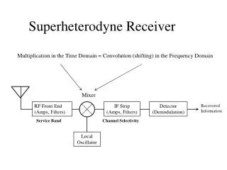
How do you measure these Specifications. • Sig Gen #1 (-120 dBm) • 6bB Attenuator • Hybrid Combiner(-6dB) Attenuator(-5dB) RX under Test Audio VM • -137dBm Noise +3dB • 6 DB Attenuator • Sig Gen #2 (No Output)
Signal to Noise Ratio • This is the input signal to the receiver compared to the noise level. This is difficult to measure because the exact contributions from each source cannot be easily determined. • A more useful term is the Signal Plus Noise to Noise (S+N/N) • S+N/N is defined as the input level to the receiver that exceeds the noise level by 10db. • Connect and set the signal generator output to the receiver frequency and to zero output level.
SN +N / N continued • Set the receiver RF gain to maximum, Turn off the AGC if possible, Then adjust the audio gain for a measurable output on a True RMS voltmeter across the speaker or phones output. Make sure this level is well below limiting in the audio stages of the receiver. Increase the signal generator output until the output level increases by 10db (3.16 X the first reading). • Record the output. This may be either in dBm or in uV.
Minimum Discernable Signal • The MDS is measured the same way as SN+N/N is measured except the signal generator output is adjusted to increase the output by 3db (1.4 X the first reading). • The MDS must be interpreted carefully because it is bandwidth dependent. • MDS(dBm) = -174dBm + 10logBWn + NF • -174dBm is the “perfect noise level of a system at room temperature (290 K) and 1Hz bandwidth.
MDS continued • Back to the real world. All receivers do generate some noise and they all have a finite bandwidth. • Noise Power vs Filter Bandwidth. • Filter Bandwidth 10 logBWn • 3.0 KHz 34.8 dB • 2.0 KHz 33.0 dB • 1.5 KHz 31.8 dB • 1.0 KHz 30.0 dB
500 Hz 27.0 dB • 300 Hz 24.8 dB • No real standard for the bandwidth used to measure MDS exists however many manufactures state the bandwidth used for both SSB and CW. • There is little that you can do about NF (noise figure) however it can be determined by rearranging the equation. NF(db) = - 174 +MDS +10 log BWn
Comparing S/N ratio to MDS • Since s + N /N is 10 dB above noise and MDS is 3 dB above noise the two can be compared by subtracting 7db from the SNR to obtain the equivalent MDS. Adjust for bandwidth from above.
Gain Compression • Gain compression is measured by recording the inpul level from the signal generator versus the output the calculating the gain from Gain = E out / E in. The signal generator output is increased until the determined gain drops by 1 dB.
Desensitization • A variation of the gain compression test is to use two signal generators, one set to the receive frequency and the second set 10 - 20 KHz away. The second generator output is increased until the receive output decreased by 1 dB.
Dynamic Range • No radio can process an infinite range of signal levels. The difference between MDS and the 1 db compression point is definned as the dynamic range.
Blocking Dynamic range Test • Sig Gen #1 (-120 dBm) • 6bB Attenuator • Hybrid Combiner(-6dB) Attenuator(-5dB) RX under Test Audio VM • Decreases 1dB • 6 dB Attenuator • Sig Gen #2 (-16dBm)
Third Order Intercept (3IP) • 3IP is a theoretical value and cannot be directly measured. • For a real world example assume that you are receiving a signal on 7.040 MHz and there is another signal at 7.050 MHz.This will produce an IMD product in your receiver about 60 dB down at 7.030 and 7.060. However due to the square law behavior of a detector if the station at 7.050 gets 10 dB louder the IMD products will get 30 dB louder.
If the signal at 7.050 gets another 10 dB louder the IMD product gets another 30 dB louder, is now 0 dB below or exactly the same level as the station you are trying to receive at 7.040. The 3rd order IMD product has intercepted the primary signal of interest, hence the name 3rd Order Intercept. • This cannot be measured due to gain compression however it can be plotted graphically to determine the 3IP.
Receiver Intermod Test • Sig Gen #1 (-10 dBm) • 6bB Attenuator • Hybrid Combiner(-6dB) Attenuator(-34dB) RX under Test Audio VM • -56dBm Noise +3dB • 6 dB Attenuator • Sig Gen #2 (-10dBm)
104 db Blocking Dynamic Range 81 dB IMD Dynamic Range -174dBm -137dBm -56dBm -33dBm 0dBm
Selectivity • This is the ability to differential between the desired signal and all other signals.. • In most receivers the selectivity is developed by front end filters. The If filters, and in some cases audio filters. • Tune the signal generator for a peak reading. then tune both above and below peak for one half the peak reading. This is the -6dB point. It is important to tune on both sides as most filters are not symmetrical.
REpeat for the -60 dB points (peak X 0.001) Say the bandwidth at -6 dB is 1.2 KHz, and 3.5 KHz at -60 dB. These filter bandwidth is 1.2 KHz. and the shape factor is 3.5khZ / 1.2 KHz = 2.9:1 • It is important to use signal generators that can resolve at least 50 Hz to properly measure these bandwidths. Repeat for all bandwidths and with the audio filter on to get it’s contribution.