Download
1 / 52
520 likes | 750 Views
Detectors for Slow Neutrons Tenth National School on Neutron and X-ray Scattering 24 September-11 October 2008. John M. Carpenter IPNS, SNS 26 September 2008 I acknowledge the assistance of Thom Mason, Kent Crawford and Ron Cooper in assembling these materials. Neutron Detectors.

E N D
Detectors for Slow NeutronsTenth National School on Neutron and X-ray Scattering24 September-11 October 2008 John M. Carpenter IPNS, SNS 26 September 2008 I acknowledge the assistance of Thom Mason, Kent Crawford and Ron Cooper in assembling these materials.
Neutron Detectors • How does one “detect” a neutron? • Can’t directly detect slow neutrons (neutrons relevant to materials science, that is)—they carry too little energy • Need to produce some sort of measurable quantitative (countable) electrical signal • Need to use nuclear reactions to convert neutrons into charged particles • Then one can use some of the many types of charged particle detectors • Gas proportional counters and ionization chambers • Scintillation detectors • Semiconductor detectors
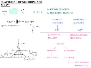
Nuclear Reactions for Neutron Detectors • n + 3He 3H + 1H + 0.764 MeV • n + 6Li 4He + 3H + 4.79 MeV • n + 10B 7Li* + 4He7Li + 4He +2.31 MeV+ gamma (0.48 MeV) (93%)7Li + 4He +2.79 MeV ( 7%) • n + 14N 14C + 1H + 0.626 MeV • n + 155Gd Gd* gamma-ray spectrum + conversion electron spectrum (~70 keV) • n + 157Gd Gd* gamma-ray spectrum + conversion electron spectrum (~70 keV) • n + 235U xn + fission fragments + ~160 MeV (<x> ~ 2.5) • n + 239Pu xn + fission fragments + ~160 MeV (<x> ~ 2.5) • 197Au(4.906 eV), 115In( 1.46 eV), 181Ta(4.28 eV), 238U(6.67, 10.25 eV); energy-selective detectors, narrow resonances, prompt capture gamma rays
Gas Detectors ~25,000 ions and electrons (~4´10-15 coulomb) produced per neutron
Gas Detectors Ionization tracks in proportional counter gas Electrons drift toward the central anode wire. When they get close, they accelerate sufficiently between collisions with gas atoms to ionize the next atom. A Townsend avalanche occurs in which the number of electrons (and ions) increases the number many-fold, about x103. Separation of these charges puts a charge on the detector, which is a low-capacitance capacitor, causing a pulse in the voltage that can be amplified and registered electronically.
Gas Detectors – cont’d • Ionization Mode • Electrons drift to anode, producing a charge pulse with no gas multiplication. • Typically employed in low-efficiency beam-monitor detectors. • Proportional Mode • If voltage is high enough, electron collisions ionize gas atoms producing even more electrons. • Gas amplification increases the collected charge proportional to the initial charge produced. • Gas gains of up to a few thousand are possible, above which proportionality is lost.
Gas Detectors – cont’d • Proportional counters (PCs) come in a variety of different forms. • Simple detector (shown previously) • Linear position-sensitive detector (LPSD): • The anode is resistive, read out from both ends—the charge distributes between the ends according to the position of the neutron capture event in the tube. • Usually cylindrical. • 2-D position-sensitive detector (MWPC). • Many parallel resistive wires extend across a large thick area of fill gas. Each wire operates either as in LPSD or without position information as in a simple PC. or • Two mutually perpendicular arrays of anode wires. Each is read separately as an LPSD to give two coordinates for the neutron capture event. • MWPCs usually have a planar configuration.
Pulse Height Discrimination-cont’d • Can set discriminator levels to reject undesired events (fast neutrons, gammas, electronic noise). • Pulse-height discrimination can make a large improvement in background. • Discrimination capabilities are an important criterion in the choice of detectors (3He gas detectors are very good).
Multi-Wire Proportional Counter • Array of discrete detectors. • Remove walls to get multi-wire counter.
MWPC-cont’d • Segment the cathode to get x-y position
Resistive Encoding of a Multi-Wire Detector • Instead of being read individually, the cathode strips can be resistively coupled (cheaper & slower) and read together. • Position of the event can be determined from the fraction of the charge reaching each end of the resistive network (charge-division encoding) • Used on the GLAD and SAND linear PSDs at IPNS.
Resistive Encoding of a Multi-Wire Detector-cont’d • Position of the event can also be determined from the relative time of arrival of the pulse at the two ends of the resistive network (rise-time encoding). • Used on the POSY1, POSY2, SAD, and SAND 2-D PSDs. • A pressurized gas mixture surrounds the electrodes.
Micro-Strip Gas Counter • Electrodes printed lithographically, producing small features. Implies • High spatial resolution. • High field gradients. • Charge localization. • Fast recovery.
Sizes of Proportional Counters • PCs and LPSDs come in many sizes. - Diameters from ~ 5. mm to 50 mm. - Fill gas pressures are highest for small diameters, up to 40 atm, and lowest for large diameters 2.~ 3. atm. - Lengths vary from cm to meters; the longer detectors, up to about 3. m long, are typically those of larger diameter. • MWPCs are usually flat and square, but sometimes rectangular, even curved, or banana-shaped. -Typical dimension 0.5 ~ 1.0 m.
Efficiency of Detectors Detectors rarely register all the incident neutrons. The ratio of the number registered to the number incident is the efficiency. • Full expression: effy= 1 - exp(-N sigma d). • Approximate expression for low efficiency: • effy= Nsigmad. • Here: • sigma= absorption cross-section (function of wavelength) • N = number density of absorber • d = thickness • N = 2.7 x 1019 cm-3per atm for a gas at 300 K. • For 1-cm thick 3He at 1 atm and 1.8-Å neutrons, = 0.13.
Efficiency of Detectors The efficiency is easy to compute in a planar detector, but more complicated in a cylindrical one: . Here, R is the radius of the detector and Sigma(lambda) is the macroscopic capture cross section of the fill gas for neutrons of wavelength lambda. Expanding the exponential in a power series gives , where x = Sigma(lambdaR, and in which pi/4, 3pi/4, 5/8pi/4, … for n = 1, 3, 5 … = 2/3, 8/15, 48/105, …for n = 2, 4, 6 … .
Spatial Resolution of Proportional Counters Spatial resolution (how well the detector tells the location of an event) is always limited by the charged-particle range and by the range of neutrons in the fill gas, which depend on the pressure and composition of the fill gas. And by the geometry: Simple PCs: d z ~ diameter; 6 mm - 50 mm. LPSDs: d z ~ diameter, d y ~ diameter ; 6 mm - 50 mm. MWPC: d z and d y ~ wire spacing; 1 mm - 10 mm.
Time Resolution of Detectors The time resolution, that is, the variance of the time of arrival of a neutron compared to the time that it passes its mean distance, is st2 = [<t2> - <t>2] = [<x2> - <x>2]/v2= sx2 /v2. Because in most converter materials the absorption cross section is inversely proportional to the neutron speed v, v sigma(v) = constant = vosigma(vo). This is the inverse lifetime of neutrons in an infinite medium of the absorber, and is independent of the neutron speed for most converters. The time resolution depends entirely on the geometric part sx2, but because sx2 depends on (v) in a more-or-less complicated way, st2 also depends on the speed. However, for infinitely thick detectors, the time resolution is constant and is equal to the lifetime of neutrons in the medium, st = 1/[vsigma(v)] = 1/[vosigma(vo)].
Some Common Scintillators for Neutron Detectors Intrinsic scintillators contain small concentrations of ions (“wave shifters”) that shift the wavelength of the originally emitted light to the longer wavelength region easily sensed by photomultipliers. ZnS(Ag) is the brightest scintillator known, an intrinsic scintillator that is mixed heterogeneously with converter material, usually Li6F in the “Stedman” recipe, to form scintillating composites. These are only semitransparent. But it is somewhat slow, decaying with ~ 10 µsec halftime. GS-20 (glass,Ce3+) is mixed with a high concentration of Li2O in the melt to form a material transparent to light. Li6Gd(BO3)3 (Ce3+) (including 158Gd and 160Gd, 6Li ,and 11B), and 6LiF(Eu) are intrinsic scintillators that contain high proportions of converter material and are typically transparent. An efficient gamma ray detector with little sensitivity to neutrons, used in conjunction with neutron capture gamma-ray converters, is YAP (yttrium aluminum perovskite, YAl2O3(Ce3+)).
Material Density of 6Li atoms (cm-3) Scintillation efficiency Photon wavelength (nm) Photons per neutron Some Common Scintillators for Neutron Detectors-cont’d 0.45 % Li glass (Ce) 1.75x10²² 395 nm ~7,000 2.8 % 470 ~51,000 LiI (Eu) 1.83x10²² 9.2 % ZnS (Ag) - LiF 1.18x10²² 450 ~160,000 Li6Gd(BO3)3 (Ce), ~40,000 3.3x10²² ~ 400 NA YAP 350 ~18,000 per MeV gamma
Principle of Crossed-Fiber Position-Sensitive Scintillation Detector Outputs to multi-anode photomultiplier tube 1-mm-square wavelength- -shifting fibers Outputs to coincidence-encoded single-anode photomultiplier tubes Scintillator screen
16-element WAND Prototype Schematic and Results Clear Fiber 2-D tube Coincidence tube Neutron Beam Wavelength-shifting fiber Aluminum wire Scintillator Screen
Crossed-Fiber Scintillation Detector Design Parameters (ORNL I&C) • Size: 25-cm x 25-cm. • Thickness: 2-mm. • Number of fibers: 48 for each axis. • Multi-anode photomultiplier tube: Phillips XP1704. • Coincidence tube: Hamamastu 1924. • Resolution: < 5 mm. • Shaping time: 300 nsec. • Counting-rate capability: ~ 1 MHz. • Time-of-flight resolution: 1 msec.
SNS 2-D Scintillation Detector Module Shows scintillator plate with all fibers installed and connected to multi-anode photomultiplier mount.
Neutron Scattering from Germanium Crystal Using Crossed-Fiber Detector • Normalized scattering from 1-cm-high germanium crystal. • En ~ 0.056 eV. • Detector 50 cm from crystal.
Neutron Detector Screen Design The scintillator screen for this 2-D detector consists of a mixture of 6LiF and silver-activated ZnS powder in an optical grade epoxy binder. Neutrons incident on the screen react with the 6Li to produce a triton and an alpha particle. These charged particles passing through the ZnS(Ag) cause it to emit light at a wavelength of approximately 450 nm. The 450-nm photons are absorbed in the wavelength-shifting fibers where they convert to 520-nm photons, some of which travel toward the ends of the fibers guided by critical internal reflection. The optimum mass ratio of 6LiF:ZnS(Ag) is about 1:3. The screen is made by mixing the powders with uncured epoxy and pouring the mix into a mold. The powder settles to the bottom of the mold before the binder cures. The clear epoxy above the settled powder mix is machined away. The mixture of 40 mg/cm2 of 6LiF and 120 mg/cm2 of ZnS(Ag) used in this screen provides a measured neutron conversion efficiency of over 90% for 1.8 Å neutrons.
Spatial Resolution of Area Scintillation Detectors The spatial resolution accomplishable in SDs is typically better than in gas detectors. The range of neutrons is less. The range of ionizing particles is less in solid materials than in gases. However, the localization of the light source (an optical process) imposes the limit on position resolution. This in turn depends statistically on the number of photons produced in the scintillator (more is better, of course). 2000-03449/arb
Anger Camera Principle Light incident on the ith photosensitive element located at position xi registers as intensity Ci. The intensity-weighted intensities provide the average position . The result is an electronic signal that is binned more finely than the size of the photosensitive elements, with a precision limited by the number of photons collected as Ci. The process is actually carried out in two dimensions. 2000-03449/arb
Anger Camera Concept for the Single- Crystal Diffractometer at SNS • Air gaps and coupling plate thicknesses arranged to limit light spread • Photomultiplier outputs are resistively encoded to give x and y coordinates. • Entire assembly is in a light-tight box.
Anger Camera for the IPNS Single-Crystal Diffractometer at IPNS The photomultipliers are nominally 1 inch square.
Hamamatsu Multicathode Photomultiplier Compact photomultipliers are essential components of scintillation area detectors. The figure shows a recently developed multicathode photomultiplier, Hamamatsu model 8500.
Semiconductor Detectors 6Li-loaded semiconductor
Semiconductor Detectors-cont’d • ~1,500,000 holes and electrons produced per neutron (~2.410-13 coulomb). • The detector acts as a capacitor. The ionization partially discharges the capacitor and can be detected directly without further amplification. • However, standard device semiconductors do not contain enough neutron-absorbing nuclei to give reasonable neutron detection efficiency. • Put neutron absorber on surface of semiconductor? These exist and are called surface barrier detectors. • Develop, for example, boron phosphide semiconductor devices? This is a challenge for future development.
Coating with Neutron Absorber-Surface-Barrier Detectors • Layer (6Li or 10B) must be thin (a few microns) for charged particles to reach the detector. • Detection efficiency is low. • Most of the deposited energy doesn’t reach detector. • Poor pulse-height discrimination
Position Encoding Methods • Discrete - One electrode per position • Discrete detectors. • Multi-wire proportional counters(MWPC). • Fiber-optic encoded scintillators (e.g., GEM detectors). • Weighted Network (e.g., MAPS LPSDs). • Rise-time encoding. • Charge-division encoding. • Anger camera. • Integrating. • Photographic film. • TV. • CCD. • Image plates.
Image Plates • Neutron-sensitive image plates (IPs) are relatively new on the scene. The converter is gadolinium, in which the capturing isotopes are • 155Gd and 157Gd, which have huge low-energy cross sections because of resonances at about 100 meV. • At higher energies, the cross sections fall off from their low-energy resonance values, so IPs are mostly useful for slow neutrons. • Sensitivity returns at eV energies because of capture resonances there.
Image Plates-cont’d Neutron capture produces prompt “conversion electrons” of rather low energy, ~ 70 keV, as well as a cascade of higher energy gamma rays. The image plate consists of finely mixed particles of converter, Gd2O3, with “storage phosphors” such as BaFBr:Eu2+ having long-lived light-emitting states that are excited by the 70-keV electrons, bonded and supported by a flexible polymer sheet. A ceramic IP has been developed, based on KCl:Eu2+ with LiF converter. These have lower neutron sensitivity than the Gd-based ones but relatively lower gamma-ray sensitivity. IPs are time-integrating detectors, providing no useful timing signals. Moreover, they are slightly sensitive to gamma rays
Image Plates-cont’d After exposure to neutrons, the plates pass through a “reader” that scans the surface with a laser beam. The laser stimulates emission of de-excitation light from the phosphor material that registers in a photosensor. The connected readout computer registers the position-dependent light intensity, providing a numerical file that can be manipulated and displayed in computer-accessible format such as color-contour diagrams of the area density of the neutron capture intensity. The plates are re-usable after “erasing” by exposure to UV light. IPs are rather like x-ray film and available in ~ 300 x 400 mm2 size. Position resolution is excellent, < 100 microns, because of the short range of the 70-keV electrons.
Picture of an Image Plate Image plates are about 20 x 30 cm in size, and look like a blank piece of paper, about 2 mm thick.
Resonance Capture Gamma-Ray Neutron Detectors Some spectrometers use detectors that register prompt capture gamma rays that are given off when an absorber (converter) captures a neutron in a sharply defined resonance (which defines the neutron energy). A closely located scintillator responds to incident gamma rays, and a coupled photomultiplier registers the pulse. The gamma-ray spectrum is specific to the compound nucleus formed in the capture. The electronics sometimes selects specific prominent lines of the spectrum, but more commonly responds to the entire shower of capture gamma rays. An RD is really more than a detector. It is a monochromating device (almost—it responds to several specific energies, which can be sorted out in time-of-flight applications).
Total Cross Section of Tantalum Tantalum is essentially monoisotopic 181Ta and is often used as a neutron converter sensitive to energies near 4.28 eV.
The 4.28-eV Resonance of Ta181 The resonance is of Breit-Wigner form and quite narrow, with resonance width = 57 meV. Thermal motions broaden the resonance significantly (green curve). The observed resonance appears broadened by resolution (blue curve).
Summary • Detectors as well as sources constrain what can be done in neutron scattering instruments. There is a continuing need for improvements. - Efficiency. - Time response. High counting rates. Sharp time determination. - Spatial resolution. • Doubling the capability of detectors to double the effectiveness of a neutron scattering instrument at a cost of, say, $1M, is far more effective than doubling the intensity of a neutron source for $1B.