Crystal Structures
Crystal Structures. Types of crystal structures Face centered cubic (FCC) Body centered cubic (BCC) Hexagonal close packed (HCP) Close Packed Structures Different Packing of HCP and FCC Crystallographic Directions and Planes cubic systems. Face Centered Cubic (FCC).

Crystal Structures
E N D
Presentation Transcript
Crystal Structures • Types of crystal structures • Face centered cubic (FCC) • Body centered cubic (BCC) • Hexagonal close packed (HCP) • Close Packed Structures • Different Packing of HCP and FCC • Crystallographic Directions and Planes • cubic systems
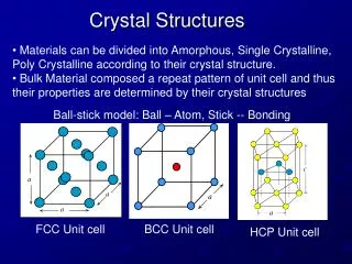
Face Centered Cubic (FCC) • Atoms are arranged at the corners and center of each cube face of the cell. • Atoms are assumed to touch along face diagonals
Face Centered Cubic (FCC) • The lattice parameter, a, is related to the radius of the atom in the cell through: • Coordination number: the number of nearest neighbors to any atom. For FCC systems, the coordination number is 12.
Face Centered Cubic (FCC) • Atomic Packing Factor: the ratio of atomic sphere volume to unit cell volume, assuming a hard sphere model. • FCC systems have an APF of 0.74, the maximum packing for a system in which all spheres have equal diameter.
Body Centered Cubic • Atoms are arranged at the corners of the cube with another atom at the cube center.
Body Centered Cubic • Since atoms are assumed to touch along the cube diagonal in BCC, the lattice parameter is related to atomic radius through:
Body Centered Cubic • Coordination number for BCC is 8. Each center atom is surrounded by the eight corner atoms. • The lower coordination number also results in a slightly lower APF for BCC structures. BCC has an APF of 0.68, rather than 0.74 in FCC
Hexagonal Close Packed • Cell of an HCP lattice is visualized as a top and bottom plane of 7 atoms, forming a regular hexagon around a central atom. In between these planes is a half-hexagon of 3 atoms.
Hexagonal Close Packed • There are two lattice parameters in HCP, a and c, representing the basal and height parameters respectively. In the ideal case, the c/a ratio is 1.633, however, deviations do occur. • Coordination number and APF for HCP are exactly the same as those for FCC: 12 and 0.74 respectively. • This is because they are both considered close packed structures.
Close Packed Structures • Even though FCC and HCP are close packed structures, they are quite different in the manner of stacking their close packed planes. • Close packed stacking in HCP takes place along the c direction ( the (0001) plane). FCC close packed planes are along the (111). • First plane is visualized as an atom surrounded by 6 nearest neighbors in both HCP and FCC.
Close Packed Structures • The second plane in both HCP and FCC is situated in the “holes” above the first plane of atoms. • Two possible placements for the third plane of atoms • Third plane is placed directly above the first plane of atoms • ABA stacking -- HCP structure • Third plane is placed above the “holes” of the first plane not covered by the second plane • ABC stacking -- FCC structure
Crystallographic Directions • Cubic systems • directions are named based upon the projection of a vector from the origin of the crystal to another point in the cell. • Conventionally, a right hand Cartesian coordinate system is used. • The chosen origin is arbitrary, but is always selected for the easiest solution to the problem.
Crystallographic Directions • Points within the lattice are written in the form h,k,l, where the three indices correspond to the fraction of the lattice parameters in the x,y,z direction.
Miller Indices • Procedure for writing directions in Miller Indices • Determine the coordinates of the two points in the direction. (Simplified if one of the points is the origin). • Subtract the coordinates of the second point from those of the first. • Clear fractions to give lowest integer values for all coordinates
Miller Indices • Indices are written in square brackets without commas (ex: [hkl]) • Negative values are written with a bar over the integer. • Ex: if h<0 then the direction is
Miller Indices • Crystallographic Planes • Identify the coordinate intercepts of the plane • the coordinates at which the plane intercepts the x, y and z axes. • If a plane is parallel to an axis, its intercept is taken as ¥. • If a plane passes through the origin, choose an equivalent plane, or move the origin • Take the reciprocal of the intercepts
Miller Indices • Clear fractions due to the reciprocal, but do not reduce to lowest integer values. • Planes are written in parentheses, with bars over the negative indices. • Ex: (hkl) or if h<0 then it becomes • ex: plane A is parallel to x, and intercepts y and z at 1, and therefore is the (011). Plane B passes through the origin, so the origin is moved to O’, thereby making the plane the