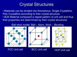
Crystal structures
Crystal structures. When we look around much of what we see is non-crystalline (organic things like wood, paper, sand; concrete walls, etc. some of the things may have some crystalline parts!).

Crystal structures
E N D
Presentation Transcript
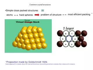
When we look around much of what we see is non-crystalline (organic things like wood, paper, sand; concrete walls, etc. some of the things may have some crystalline parts!). • But, many of the common ‘inorganic’ materials are ‘usually*’ crystalline:◘ Metals: Cu, Zn, Fe, Cu-Zn alloys◘ Semiconductors: Si, Ge, GaAs ◘ Ceramics: Alumina (Al2O3), Zirconia (Zr2O3), SiC, SrTiO3
Why study crystal structures? • The crystal structure directly influences the properties of the material • Gives a brief (concise) representation of a large assemblage of species • Gives the ‘first view’ towards understanding of the properties of the crystal
Before the development of X-ray diffraction crystallography, the study of crystals was based on their geometry. This involves 1. Measuring the angles of crystal faces relative to theoretical reference axes (crystallographic axes), 2. Establishing the symmetry of the crystal. The position in 3D space of each crystal face is plotted on a stereographic net (Wulff net or Lambert net). Each point is labeled with its Miller index. The final plot allows the symmetry of the crystal to be established
Miller indices Miller indices were introduced in 1839 by the British mineralogist William Hallowes Miller. Miller indices form a notation system in crystallography for planes in crystal (Bravais) lattices. It is introduced to specify the plane or direction in a crystal lattice.
Miller Indices An ordered surface may be obtained by cutting the three-dimensional bulk structure of a solid along a particular plane to expose the underlying array of atoms. The way in which this plane intersects the three-dimensional structure is very important and is defined by using Miller Indices- This notation is commonly used by both surface scientists and crystallographers.
The orientation of a surface or a crystal plane may be defined by considering how the plane intersects the main crystallographic axes of the solid. The application of a set of rules leads to the task of the Miller Indices , (hkl) ; a set of numbers which quantify the intercepts and thus may be used to uniquely identify the plane or surface.
For a crystal plane, the Miller indices can be obtained through the following three steps: STEP--1 STEP--2 STEP--3 Take reciprocals of the fractions, and put them in a pair of curved brackets (hkl) Find the intersections of the plane on the three axes (a, b, and c) of the unit cell Represent the intersections as fractions of the lattice constant, e.g., a/h; b/k; c/l
Miller Indices: How to find out? 1. The intercepts made by the plane along x, y and z axis are noted 2. The coefficients of the intercepts are noted separately 3. Inverse is to be taken 4. The fraction are multiplied by a suitable number, so that all the fractions become integers 5. Write the integers within the parentheses.
Miller Indices: How to find out? 1. The intercepts made by the plane along x, y and z axis are noted Simple cubic crystal system
Step 1 : Identify the intercepts on the x, y and z axes In this case the intercept on the x-axis is at x = a ( at the point (a,0,0) ), but the surface is parallel to the y- and z-axes - strictly therefore there is no intercept on these two axes but we shall consider the intercept to be at infinity ( ∞ ) for the special case where the plane is parallel to an axis. The intercepts on the x- , y- and z-axes are thus Intercepts : a , ∞ , ∞ Intercepts : a , ∞ , ∞
Step 2 : Specify the intercepts in fractional co-ordinates Co-ordinates are converted to fractional co-ordinates by dividing by the respective cell-dimension - for example, a point (x,y,z) in a unit cell of dimensions a x b x c has fractional co-ordinates of ( x/a , y/b , z/c ). In the case of a cubic unit cell each co-ordinate will simply be divided by the cubic cell constant , a . This gives Fractional Intercepts : a/a , ∞/a, ∞/a i.e. 1 , ∞ , ∞
Step 3 : Take the reciprocals of the fractional intercepts This final manipulation generates the Miller Indices which should then be specified without being separated by any commas or other symbols. The Miller Indices are also enclosed within standard brackets (….) when one is specifying a unique surface such as that being considered here. The reciprocals of 1 and ∞ are 1 and 0 respectively, thus yielding Miller Indices : (100) *The surface/plane illustrated is the (100) plane of the cubic crystal.
Define Miller Indices ? Assignment Intercepts : a , a , ∞ Fractional intercepts : 1 , 1 , ∞ Miller Indices : (110)
Define Miller Indices ? Assignment Intercepts : a , a , a Fractional intercepts : 1 , 1 , 1 Miller Indices : (111)
Define Miller Indices ? Miller indices of the cubic planes ABCD
Miller indices of the cubic planes AEFB (100), (010) and (001)