New TURF for TIRF
410 likes | 932 Views
New TURF for TIRF. Joel Schwartz Stowers Institute for Medical Research Imaging Center. What is TIRF? Why do we constantly use acronyms to describe everything? Microscope Configurations Prism vs Prismless Biological Applications Brief Aside Unique attributes to our system

New TURF for TIRF
E N D
Presentation Transcript
New TURF for TIRF Joel Schwartz Stowers Institute for Medical Research Imaging Center
What is TIRF? • Why do we constantly use acronyms to describe everything? • Microscope Configurations • Prism vs Prismless • Biological Applications • Brief Aside • Unique attributes to our system • Calibrated TIRF planes • TIRF-FRET • TIRF-photoactivation • Not ready for prime time players..
What is TIRF? • Why do we constantly use acronyms to describe everything? • Microscope Configurations • Prism vs Prismless • Biological Applications • Brief Aside • Unique attributes to our system • Calibrated TIRF planes • TIRF-FRET • TIRF-photoactivation • Not ready for prime time players..
Index of refraction “bends” light Some refractive indices to know:
The basics of imaging cells by TIRF microscopy At a specific critical angle [θcritical = sin-1(n1/n2)] light is totally reflected from the glass/water interface. The reflection generates a very thin electromagnetic field that has an identical frequency to that of the incident light, providing a means to selectively excite fluorophores within ≤ 100 nm of the coverslip.
http://micro.magnet.fsu.edu/primer/java/tirf/penetration/index.htmlhttp://micro.magnet.fsu.edu/primer/java/tirf/penetration/index.html
Evanescent wave penetration note: d is only the depth at which the intensity of the evanescent wave is 37% of the initial intensity. Thus, can empirically determine the experimental depth at which fluorophores are visible using fluorescent beads (Keyel, Watkins, and Traub 2004 JBC) The evanescent wave penetration (d) : d = λ0/4π (n22 sin2θ-n12)-1/2 λ0 = 488; n2=1.52; n1=1.38 dempirical = 190 nm λ0 = 647; n2=1.52; n1=1.38 dempirical = 238 nm λ0 = 488; n2=1.78; n1=1.38 dempirical = 142 nm
What is TIRF? • Why do we constantly use acronyms to describe everything? • Microscope Configurations • Prism vs Prismless • Biological Applications • Brief Aside • Unique attributes to our system • Calibrated TIRF planes • TIRF-FRET • TIRF-photoactivation • Not ready for prime time players..
Prism-based TIRF limit access to sample Axelrod et al. Traffic 2001
Prism-based TIR on an upright microscope Trapezoid TIR prism on condenser and the position of the beam is adjusted by moving external lens. Axelrod et al. Traffic 2001
The objective influences penetration depth TIRF objectives are now starting to come with compensation collars for varying temperature and cover slip thickness 100X 1.45 NA objective:θc = sin-1(n1/n2) = 65.22º[calculated using n2 = 1.52 (RI coverglass and immersion liquid) and n1 = 1.38] 100X 1.65 NA objective:θc = sin -1(n1/n2) = 50.83º[calculated using n2 = 1.78 (RI coverglass and immersion liquid) and n1 = 1.38] Maximum Angle θm from the optical axis that TIR will occur is: NA = n2 sin θm 60X 1.45 NA θm = 72.54º 100X 1.65 NA θm = 67.97º
TIRF Comparison • Prism Method • “Purer” evanescent wave • Limited access to sample • Few commercial manufactures • Open laser systems • Typically lower NA objectives • Prism-less Method • Higher NA will allow confinement closer to surface • Not as pure an evanescent wave as prism • Commercial system readily available
What is TIRF? • Why do we constantly use acronyms to describe everything? • Microscope Configurations • Prism vs Prismless • Biological Applications • Brief Aside • Unique attributes to our system • Calibrated TIRF planes • TIRF-FRET • TIRF-photoactivation • Not ready for prime time players..
TIRF is more sensitive to Z-axial drift Hogan, Biophotnics International May 2006 48-51
Color Coded Motion Red Green Blue RGB
Membrane-localized fluorophores are difficult to separate from mitochondria
TIRF selectively visualizes the membrane localized fluorophores
Total Internal Reflection Fluorescence (TIRF) Microscopy is used to reduce background Applications of TIR microscopy • Selective visualization of cell/substrate contact regions. • Visualization and spectroscopy of single molecule fluorescence near a surface. • Tracking of secretory granules in intact cells before and during the secretory process. • Micromorphological structures and dynamics on living cells. • Long-term fluorescence movies of cells during development in culture. • Comparison of membrane-proximal ionic transients with simultaneous transients deeper in the cytoplasm. • Measurements of the kinetic rates of binding of extracellular and intracellular proteins to cell surface receptors and artificial membranes.
What is TIRF? • Why do we constantly use acronyms to describe everything? • Microscope Configurations • Prism vs Prismless • Biological Applications • Brief Aside • Unique attributes to our system • Calibrated TIRF planes • TIRF-FRET • TIRF-photoactivation • Not ready for prime time players..
405, 440, 491, 561, 638 AOTF operated Axiocam HS Environmental Chamber BAD IDEA! Back-thinned EM-CCD The new rig
TIRF enhances signal to noise measurements of membrane associated FRET 1 um z-axial ~ 15 receptors ~ 75 associated proteins 100 nm ~ 15 receptors ~ 15 associated proteins
We idealized the system to excite CFP for FRET measurements Excitation of CFP leads to some YFP excitation because YFP is ~5 fold brighter than CFP. CFP emission also bleeds into the YFP channel (i.e. there will always be some “FRET” signal).
The new TIRF scope is capable of specific membrane photoactivation
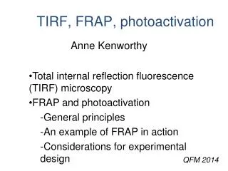
What is TIRF? • Why do we constantly use acronyms to describe everything? • Microscope Configurations • Prism vs Prismless • Biological Applications • Brief Aside • Unique attributes to our system • Calibrated TIRF planes • TIRF-FRET • TIRF-photoactivation • Not ready for prime time players..
Spectral images separate overlaping spectra Dickinson et al. Biotechniques. 31:1272 2001.
CTIS provides space and color information without any moving parts NOT YET AVAILABLE The system is a linear transfer function similar to CT scanning and reconstruction
Spectral Imaging: CTISSpace and Color in a Single Shot CGH Disperser
The CTIS images are deconvolved to generate the actual image Ford et al., Optics Express’01 (9) 444-453. Raw Data on CCD Color projection of final data stack
Imaging Center Cameron Cooper Paul Kulesa Sarah Smith Danny Stark Jessica Teddy Miranda Smith Adv. Inst. And Physics Winfried Wiegraebe Josef Huff Amanda Combs Thank You
http://micro.magnet.fsu.edu/primer/java/tirf/evaintensity/index.htmlhttp://micro.magnet.fsu.edu/primer/java/tirf/evaintensity/index.html