Download

1 / 51
570 likes | 1.38k Views
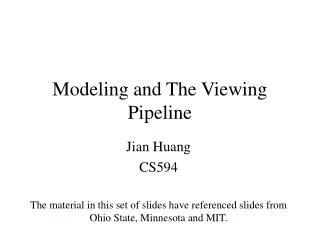
Modeling and The Viewing Pipeline Jian Huang CS594 The material in this set of slides have referenced slides from Ohio State, Minnesota and MIT. Modeling Types: Polygon surfaces Curved surfaces Generating models: Interactive Procedural Polygon Mesh

E N D
Modeling and The Viewing Pipeline Jian Huang CS594 The material in this set of slides have referenced slides from Ohio State, Minnesota and MIT.
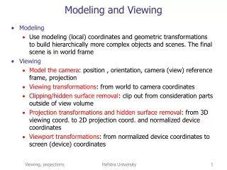
Modeling • Types: • Polygon surfaces • Curved surfaces • Generating models: • Interactive • Procedural
Polygon Mesh • Set of surface polygons that enclose an object interior, polygon mesh • De facto: triangles, triangle mesh.
Representing Polygon Mesh • Vertex coordinates list, polygon table and (maybe) edge table • Auxiliary: • Per vertex normal • Neighborhood information, arranged with regard to vertices and edges
Arriving at a Mesh • Use patches model as implicit or parametric surfaces • Beziér Patches : control polyhedron with 16 points and the resulting bicubic patch:
Example: The Utah Teapot • 32 patches single shaded patch wireframe of the control points Patch edges
Patch Representation vs. Polygon Mesh • Polygons are simple and flexible building block. • But, a parametric representation has advantages: • Conciseness • A parametric representation is exact and analytical. • Deformation and shape change • Deformations appear smooth, which is not generally the case with a polygonal object.
Common Polyhedral Shape Construction Operations • Extrude: add a height to a flat polygon • Revolve: Rotate a polygon around a certain axis • Sweep: sweep a shape along a certain curve (a generalization of the above two) • Loft: shape from contours (usually in parallel slices) • Set operations (intersection, union, difference), CSG (constructive solid geometry) • Rounding operations: round a sharp corner
Constructive Solid Geometry (CSG) • To combine the volumes occupied by overlapping 3D shapes using set operations. intersection difference union
F P P Pinhole Model • Visibility Cone with apex at observer • Reduce hole to a point - the cone becomes a ray • Pin hole - focal point, eye point or center of projection.
Filling Algorithms - Flood Fill • flood_fill (x, y, old_color, new_color, connectivity) • if read_pixel(x, y) = old_color then • draw_pixel(x, y, new_color); • recursive_call(x, y, old_color, new_color, connectivity); • end_if; EYE OBJECT WORLD Transformations – Need ? • Modeling transformations • build complex models by positioning simple components • Viewing transformations • placing virtual camera in the world • transformation from world coordinates to eye coordinates • Side note: animation:vary transformations over time to create motion
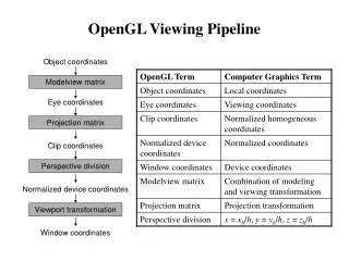
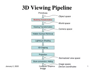
Object Space World Space Eye Space Clipping Space Screen Space Viewing Pipeline Canonical view volume • Object space: coordinate space where each component is defined • World space: all components put together into the same 3D scene via affine transformation. (camera, lighting defined in this space) • Eye space: camera at the origin, view direction coincides with the z axis. Hither and Yon planes perpendicular to the z axis • Clipping space: do clipping here. All point is in homogeneous coordinate, i.e., each point is represented by (x,y,z,w) • 3D image space (Canonical view volume): a parallelpipied shape defined by (-1:1,-1:1,0,1). Objects in this space is distorted • Screen space: x and y coordinates are screen pixel coordinates
Spaces: Example Object Space and World Space: Eye-Space:
Spaces: Example • Clip Space: • Image Space:
2D Transformation • Translation • Rotation
Homogeneous Coordinates • Matrix/Vector format for translation:
Translation in Homogenous Coordinates • There exists an inverse mapping for each function • There exists an identity mapping
Why these properties are important • when these conditions are shown for any class of functions it can be proven that such a class is closed under composition • i. e. any series of translations can be composed to a single translation.
Rotation in Homogeneous Space The two properties still apply.
Putting Translation and Rotation Together • Order matters !!
Affine Transformation • Property: preserving parallel lines • The coordinates of three corresponding points uniquely determine any Affine Transform!!
Affine Transformations T • Translation • Rotation • Scaling • Shearing
How to determine an Affine 2D Transformation? • We set up 6 linear equations in terms of our 6 unknowns. In this case, we know the 2D coordinates before and after the mapping, and we wish to solve for the 6 entries in the affine transform matrix
Affine Transformation in 3D • Translation • Rotate • Scale • Shear
More Rotation • Which axis of rotation is this?
Viewing • Object space to World space: affine transformation • World space to Eye space: how? • Eye space to Clipping space involves projection and viewing frustum
Image W F I World Perspective Projection and Pin Hole Camera • Projection point sees anything on ray through pinhole F • Point W projects along the ray through F to appear at I (intersection of WF with image plane)
Image Formation Image F World Projecting shapes • project points onto image plane • lines are projected by projecting its end points only
World Image F W Image I F World Orthographic Projection • focal point at infinity • rays are parallel and orthogonal to the image plane
Simple Perspective Camera • camera looks along z-axis • focal point is the origin • image plane is parallel to xy-plane at distance d • d is call focal length for historical reason
Y [Y, Z] [(d/Z)Y, d] Z [0, 0] [0, d] Similar Triangles • Similar situation with x-coordinate • Similar Triangles: point [x,y,z] projects to [(d/z)x, (d/z)y, d]
é ù é ù d 0 0 0 x ê ú ê ú é ù 0 d 0 0 y d d ê ú ê ú [ ] = Þ dx dy dz z x y d ê ú ê ú ê ú ë û 0 0 d 0 z z z ê ú ê ú ê ú ê ú ë 0 0 1 0 û ë 1 û Divide by 4th coordinate (the “w” coordinate) Projection Matrix • Projection using homogeneous coordinates: • transform [x, y, z] to [(d/z)x, (d/z)y, d] • 2-D image point: • discard third coordinate • apply viewport transformation to obtain physical pixel coordinates
View Volume • Defines visible region of space, pyramid edges are clipping planes • Frustum :truncated pyramid with near and far clipping planes • Near (Hither) plane ? Don’t care about behind the camera • Far (Yon) plane, define field of interest, allows z to be scaled to a limited fixed-point value for z-buffering.
Difficulty • It is difficult to do clipping directly in the viewing frustum
Canonical View Volume • Normalize the viewing frustum to a cube, canonical view volume • Converts perspective frustum to orthographic frustum – perspective transformation
Perspective Transform • The equations alpha = yon/(yon-hither) beta = yon*hither/(hither - yon) s: size of window on the image plane z’ alpha 1 z yon hither
About Perspective Transform • Some properties
About Perspective Transform • Clipping can be performed against the rectilinear box • Planarity and linearity are preserved • Angles and distances are not preserved • Side effects: objects behind the observer are mapped to the front. Do we care?
Perspective + Projection Matrix • AR: aspect ratio correction, ResX/ResY • s= ResX, • Theta: half view angle, tan(theta) = s/d
Camera Control and Viewing Focal length (d), image size/shape and clipping planes included in perspective transformation • r Angle or Field of view (FOV) • AR Aspect Ratio of view-port • Hither, YonNearest and farthest vision limits (WS). Lookat - coi Lookfrom - eye View angle - FOV
Complete Perspective • Specify near and far clipping planes - transform z between znear and zfar on to a fixed range • Specify field-of-view (fov) angle • OpenGL’s glFrustum and gluPerspective do these
More Viewing Parameters • Camera, Eye or Observer: • lookfrom:location of focal point or camera • lookat: point to be centered in image • Camera orientation about the lookat-lookfromaxis • vup: a vector that is pointing straight up in the image. This is like an orientation.
Implementation … Full Blown • Translate by -lookfrom, bring focal point to origin • Rotate lookat-lookfrom to the z-axis with matrix R: • v = (lookat-lookfrom) (normalized) and z = [0,0,1] • rotation axis: a = (vxz)/|vxz| • rotation angle: cos = a•z and sin = |rxz| • OpenGL:glRotate(, ax, ay, az) • Rotate about z-axis to get vup parallel to the y-axis
Viewport mapping • Change from the image coordinate system (x,y,z) to the screen coordinate system (X,Y). • Screen coordinates are always non-negative integers. • Let (vr,vt) be the upper-right corner and (vl,vb) be the lower-left corner. • X = x * (vr-vl)/2 + (vr+vl)/2 • Y = y * (vt-vb)/2 + (vt+vb)/2
True Or False • In perspective transformation parallelism is not preserved. • Parallel lines converge • Object size is reduced by increasing distance from center of projection • Non-uniform foreshortening of lines in the object as a function of orientation and distance from center of projection • Aid the depth perception of human vision, but shape is not preserved