Download
1 / 65
660 likes | 859 Views
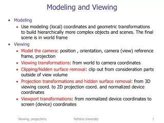
Viewing and Projections. Dr. Amy Zhang. Reading. Hill, Chapter 5 and 7 Red Book, Chapter 3, “Viewing”. 3D Graphics Pipeline. The big picture…. Outline. Camera Models Viewing Transformation Projection Matrix OpenGL Transformation Pipeline. Cameras. Cameras have an optical system:

E N D
Viewing and Projections Dr. Amy Zhang
Reading • Hill, Chapter 5 and 7 • Red Book, Chapter 3, “Viewing”
3D Graphics Pipeline • The big picture…
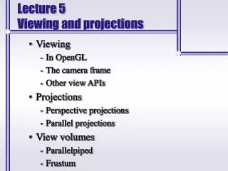
Outline • Camera Models • Viewing Transformation • Projection Matrix • OpenGL Transformation Pipeline
Cameras • Cameras have an optical system: • Filters • Lenses • Aperture • The projection surface may be flat or curved, oriented at various angles with respect to the incoming light. • Examples: A camera or the eye.
Camera Obscura • The first cameras – a dark box with a small hole in it
The Pinhole Camera • An abstract camera model • Models the geometry of perspective projection • Used in most of computer graphics
Perspective Derivation • Consider the projection of a point onto the projection plane:
By similar triangles we can compute how much the x and y-coordinates are scaled • Looking down y axis:
We get: • This is clearly a non-linear transformation • BUT: We can split it into a linear part followed by a nonlinear part
Homogeneous Coordinates • Remember homogeneous coordinates: • To get a homogeneous point we divide all the coordinates by w: • This is called the perspective divide
Perspective Projections • We can now rewrite the perspective projection as a linear transformation: • After division by the 4th component we get:
The Lens Model • Lens, aperture, and image plane
Focal length f: the distance from lens to image plane • A point in focus: the image of a point is on the image plane
An out-of-focus point • The circle of confusion r
The depth of focus dfocus and the depth of field (DOF) dfield
Decreasing the aperture size reduces the size of the blur for points not in the focused plane, so that the blurring is imperceptible, and all points are within the dfield.
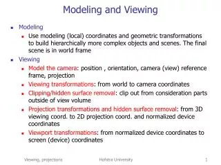
Viewing and Projection • In OpenGL we distinguish between: • Viewing: placing the camera • Projection: describing the viewing frustum of the camera (and thereby the projection transformation) • Perspective divide: computing homogeneous points
Outline • Camera Models • Viewing Transformation • Projection Matrix • OpenGL Transformation Pipeline
OpenGL Transformations • The viewing transformation V transforms a point from world space to eye space:
Placing the Camera • It is most natural to position the camera in world space as if it were a real camera • Identify the eye point where the camera is located • Identify the look-at point that we wish to appear in the center of our view • Identify an up-vector vector that we wish to be oriented upwards in our final image
Look-At Positioning • We specify the view frame using the look-at vector a and the camera up vector up • The vector a points in the negative viewing direction • In 3D, we need a third vector that is perpendicular to both up and a to specify the view frame
Where does it point to? • The result of the cross product is a vector, not a scalar, as for the dot product • Depending on the basis vectors i, j, and k, the new vector follows the right or left handed rule • In OpenGL, the cross product a x b yields a right hand side (RHS) vector perpendicular to a and b
Computing Cross Products • We can compute the cross product using yet another matrix-vector multiplication: • The matrix is sometimes called the skew-symmetric matrix of the vector (in this case a) • Cross products produce vectors for both vector and point inputs
Constructing a Frame • The cross product between the up and the look-at vector will get a vector that points to the right. • Finally, using the vector a and the vector r we can synthesize a new vector u in the up direction:
World and Camera Frames • The relation between the world and the camera is expressed as: • We move the eye (camera) by updating E
Rotation • Rotation first:
Translation • Translation to the eye point:
Composing the Result • The final camera transformation is: • Why?
The Viewing Transformation • Expressing P in eye coordinates:
The Viewing Transformation • As a single 4x4 matrix: • Where these are normalized vectors:
gluLookAt() • OpenGL provides a very helpful utility function that implements the look‐at viewing specification: • These parameters are expressed in world coordinates
Outline • Camera Models • Viewing Transformation • Projection Matrix • OpenGL Transformation Pipeline
OpenGL Transformations • The projection transformation P transforms a point from eye space to clip space:
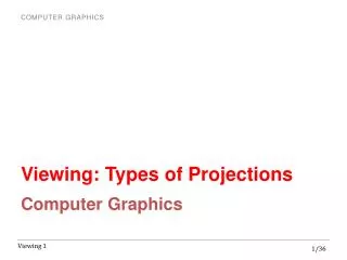
Projection Transformations • Projections fall into two categories: • Parallel projections: The camera is placed at an infinite distance from the viewplane; lines of projection are parallel to each other • Perspective projections: Lines of projection converge at a point
Parallel Projections • The simplest form of parallel projection is simply along lines parallel to the z-axis onto the xy-plane • This form of projection is called orthographic • For other parallel projections see, e.g.: http://www.mtsu.edu/~csjudy/planeview3D/tutorialparallel.html
Orthographic Frustum • The user specifies the orthographic viewing frustum by specifying minimum and maximum x/y coordinates • It is necessary to indicate a range of distances along the z-axis by specifying near and far planes
Orthographic Projections to NDC • Normalized Device Coordinate (NDC) makes up a coordinate system that describes positions on a virtual plotting device • Here is the orthographic world-to-clip transformation: • Move center to origin T(-(left+right)/2, -(bottom+top)/2,(near+far)/2)) • Scale to have sides of length 2 S(2/(right-left),2/(top-bottom),2/(far-near)) P = ST =
Orthographic Projection in OpenGL • This matrix is constructed with the following OpenGL call: • And the 2D version (another GL utility function): • Just a call to glOrtho() with near = -1 and far = +1
Properties of Parallel Projections • Not realistic looking • Good for exact measurements • A kind of affine transformation • Parallel lines remain parallel • Ratios are preserved • Angles (in general) not preserved • Most often used in CAD, architectural drawings, etc., where taking exact measurement is important
Isometric Games • A special kind of parallel projection called isometric projection is often used in games • It’s essentially a shear and an orthographic projection • Easier to compute than a full perspective transformation Diablo SimCity The Sims
Perspective Projections • Artists (Donatello, Brunelleschi, and Da Vinci) during the renaissance discovered the importance of perspective for making images appear realistic • Parallel lines intersect at a point
Perspective Viewing Frustum • Just as in the orthographic case, we specify a perspective viewing frustum • Values for left, right, top, and bottom are specified at the near depth.