Download
1 / 82
870 likes | 1.27k Views
Dive into structural engineering with a hands-on truss bridge project using file folders. Learn about design, forces, and structural analysis. Suitable for beginners with step-by-step instructions.

E N D
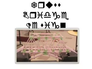
The Waddell A-Truss Bridge Designing and Building File-Folder Bridges as an Introduction to Engineering COL Stephen Ressler, P.E., Ph.D. Department of Civil & Mechanical Engineering U.S. Military Academy, West Point
Objectives • Learn about structural engineering: • Through a hands-on bridge-building project. • Through the use of free computer software. • Learn about the ongoing West Point Bridge Design Contest.
A Typical Bridge-Building Project • Students receive a pile of Popsicle sticks and some glue. • Students build a bridge, based on... • A picture. • A vague idea of what a bridge should look like. • Bridges are weighed. • Bridges are tested to failure. • Highest strength-to-weight ratio wins. What do students actually learn from this experience?
What They Don’t Learn • A systematic design process precedes construction. • Engineers design; Contractors build. • The design process is informed by math and science. • Design is iterative. • Structures are designed to carry code-specified loads safely and economically. • Designed to stand up, not to fail. • Strength-to-weight ratio is never the objective. The Essential Characteristics Of Engineering
Why File Folders? • Inexpensive. • Easy to cut, bend, and glue. • Surprisingly predictable structural behavior. • Can be used to build: • Tubes and bars. • Connections that are stronger than the attached structural members.
Our Agenda • Introduction to Truss Bridges • Start building a truss • Forces and equilibrium • Continue building the truss • Structural analysis • Finish the truss • Materials testing • Structural evaluation • Structural design • Manual method • Using the West Point Bridge Designer This allows time for the glue to dry
These concepts could be taught in the context of this project What You Need to Know • For building a file-folder bridge: • NONE • For analyzing a file-folder bridge: • Basic algebra • Geometry – Pythagorean Theorem • Trigonometry – sine and cosine • Physics – forces, equilibrium • Computers – spreadsheets • For the West Point Bridge Designer • NONE
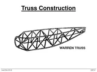
What is a Truss? • A structure composed of members connected together to form a rigid framework. • Usually composed of interconnected triangles. • Members carry load in tension or compression.
Component Parts Support (Abutment)
Types of Structural Members These shapes are called cross-sections.
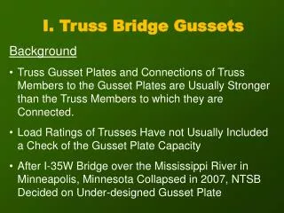
Types of Truss Connections Pinned Connection Gusset Plate Connection Most modern bridges use gusset plate connections
Let’s build this bridge... Waddel “A Truss” Bridge over Lin Branch CreekTrimble, MO
10 mm x 10 mm Tube Doubled 4 mm Bar Doubled 2 mm Bar The Design • Design Requirements: • Span–30 cm • Loading–5 kg (at midspan) We’ll talk about how it was designed later...
Materials & Equipment • File folders • Yellow carpenter’s glue • Building board (Styrofoam or cork) • Pins • Scissors • Metal ruler* • Hobby knife or single-edge razor blade* • Rubber cement* *Required only for prefabrication of structural members
Prefabrication of Members • Cut out bars • Cut out and assemble tubes • Cut out gusset plates • Trim bars and tubes to length
Trim Bars and Tubes to Length Bottom Chords(2 per team)
Trim Bars and Tubes to Length Bottom Chords (2 per team)
Trim Bars and Tubes to Length Verticals (2 per team)
Trim Bars and Tubes to Length Verticals (2 per team)
Trim Bars and Tubes to Length End Posts (2 per team)
Trim Bars and Tubes to Length End Posts (2 per team)
Set up the Building Board Each Team Member: • Place the layout drawing on your building board.
Set up the Building Board • Place a sheet of plastic wrap over the layout drawing.
Add Gusset Plates • Place Gusset Plate A at its correct location on the layout drawings. • Hold it in place with two pins.
Add Gusset Plates • Repeat the process for Gusset Plates B, C, and D.
Add Bars • Apply a line of glue along the bottom edge of Gusset Plates A, B, and C. • Place a 2 mm bar in position as the bottom chord AC. • Stretch tight and hold in place with two pins.
Add Bars • Apply glue to Gusset Plates B and D. • Place a 4 mm bar in position as the vertical member BD. • Stretch tight and hold in place with your fingers. Each team should now have two of these subassemblies —the lower half and the upper half of one truss.
Add Tubes For the bottom half of the truss (one per team): • Apply glue to Gusset Plates A and D. • Place a 10mm x 10mm tube in position as end post AD. • Hold in place for a minute until the glue sets.
Add Tubes • Apply glue to Gusset Plates C and D. • Place a 10 mm x 10 mm tube in position as end post AD. • Hold in place for a minute until the glue sets.
Add Tubes • Cut a 2 cm length of 10 mm x 10 mm tube. • Apply glue to Gusset Plate B. • Place the tube vertically on the gusset plate. • Hold in place for a minute until the glue sets.
The Finished Half-Truss • Allow all glue joints to dry.
Forces, Loads, & Reactions • Force – A push or pull. • Load – A force applied to a structure. • Reaction – A force developed at the support of a structure to keep that structure in equilibrium. Self-weight of structure, weight of vehicles, pedestrians, snow, wind, etc. Forces are represented mathematically as VECTORS.
Equilibrium Newton’s First Law: An object at rest will remain at rest, provided it is not acted upon by an unbalanced force. A Load... ...and Reactions
An unloaded member experiences no deformation Tension causes a member to get longer Compression causes a member to shorten Tension and Compression
Tension and Compression EXTERNAL FORCES and INTERNAL FORCES Must be in equilibrium with each other.
Assemble the Two Halves • Pull out all of the pins on both halves of the truss. • Carefully separate the upper half of the truss from the plastic wrap. • Keep the lower half of the truss on the building board.
Assemble the Two Halves • Put glue on the tubes at A, B, C, and D. • Place the upper half onto the lower half. • Stretch the bars tight and hold until the glue has set.
Assemble the Two Halves • Allow all glue joints on the completed truss to dry.
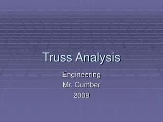
Structural Analysis • For a given load, find the internal forces (tension and compression) in all members. • Why? • Procedure: • Model the structure: • Define supports • Define loads • Draw a free body diagram. • Calculate reactions. • Calculate internal forces using “Method of Joints.”
15 cm 15 cm 15 cm Model the Structure D A B C mass=5 kg =2.5 kg per truss
15 cm 15 cm 15 cm y x Draw a Free Body Diagram D A B C RA RC mass=2.5 kg 24.5N
Calculate Reactions • Total downward force is 24.5 N. • Total upward force must be 24.5 N. • Loads, structure, and reactions are all symmetrical. RA and RC must be equal.
15 cm 12.3 N 12.3 N Calculate Reactions 15 cm 15 cm D A B C y RA RC 24.5 N x
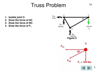
15 cm 15 cm D 15 cm B C 12.3 N RC 24.5 N Method of Joints • Isolate a Joint. A y 12.3 N x
FAD y FAB x Method of Joints • Isolate a Joint. • Draw a free body diagram ofthe joint. • Include any external loads ofreactions applied at the joint. • Include unknown internal forcesat every point where a member was cut. • Assume unknown forces in tension. • Solve the Equations of Equilibrium for the Joint. A 12.3 N EXTERNAL FORCES and INTERNAL FORCES Must be in equilibrium with each other.
FAD A y FAB 12.3 N x Equations of Equilibrium • The sum of all forces acting in the x-direction must equal zero. • The sum of all forces acting in the y-direction must equal zero. • For forces that act in a diagonal direction, we must consider both the x-component and the y-component of the force.
If magnitude of FAD is represented as the hypotenuse of a right triangle... Then the magnitudes of (FAD)x and (FAD)y are represented by the lengths of the sides. y (FAD)y q q x A (FAD)x Components of Force FAD A
Definitions: H y q x Therefore: Trigonometry Review