Download

1 / 41
430 likes | 744 Views
Tools for Evaluation of Steel Truss Bridge Gusset Plates. Christopher Higgins Quang Nguyen O. Tugrul Turan School of Civil and Construction Engineering Oregon State University. OUTLINE. INTRODUCTION & BACKGROUND. Introduction & Background.

E N D
Tools for Evaluation of Steel Truss Bridge Gusset Plates Christopher Higgins Quang Nguyen O. TugrulTuran School of Civil and Construction Engineering Oregon State University
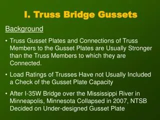
Introduction & Background Gusset plate connection performance of interest. Structural evaluations require accurate as-built data. Collection of field data is time consuming and expensive. Results likely to be highly variable. Rating methods rely on specification-based on designprovisions. Need for improved tools. Collapsed I35W Bridge in Minneapolis, MN
Overall Approach Capture images in field with digital cameras (snooper, climbing, from ground level) Process images into scaled orthophotos (MatLab) Query and extract geometric data (MatLab) Directly produce CAD drawings (AutoCAD) Directly produce FE models (ABAQUS) Run nonlinear finite element analyses to rate connections (ABAQUS) No high-level training required (scripted CAD drawing and FE modeling) Integration from field inspection to rating and archiving
Inspectors Get Creative Is there a better way?
Methodology X’ is point in photographic image plane (pixel) Gusset plates lie in plane : 2-D correspondences simplify transformation Point correspondences used to map points based on central projection. Need to establish control points in the real world image. X is point in “real world” image Hartley and Zisserman, Multiple View Geometry in Computer Vision, 2004
Methodology Relate image points (pixels) to real world control points via transformation matrix • Remove image perspective (rectification) Direct Linear Transform (DLT) algorithm H is 3x3 transformation matrix Need minimum of 4 control points (8 DOF and 1 for scale) If over constrained then can estimate errors. X and Y are point coordinates in real world image X’ and Y’are point coordinates on photographic image plane (pixles)
Methodology Reference Targets 8” and 24” Reference Targets • Ultra Corrosion-Resistant Pure Titanium (Grade 2) bars • Nine aluminum control points • Safety chain and vise-grip clamp
Methodology Base magnetically attaches and sits 2” off of the face of the plate
Error Estimation Root-Mean-Square Error: where θ’ is the predicted value, θ is the true value, and n is the sample size. Standard deviation: where e is the location error, ē is the average location error, and n is the sample size. Methodology
Error Estimation Location Uncertainty: Measurement Error for Length Measurements: where RMSE is the predicted error value, 3σ provides a 99.7% confidence interval for a normal distribution, and the given pixel size. Measurements of length require two points thus double the location uncertainty. Methodology
Methodology Distance to plate, D Standoff correction Targets are offset from plates Image dimensions are shorter than true dimensions due to standoff Correction may be performed: Actual dimension on plate Image dimension Standoff distance of targets, Doffset
Implementation Consumer grade camera • Single-lens reflex (SLR) digital camera (Nikon D200) • Nikon AF NIKKOR 50mm 1:1.8D lens • Resolution: 3872x2592 Pixels (10 Megapixel) Fill the image frame with the gusset plate as much as possible. Take a well focused image. Take the best available image with the camera as orthogonal to the gusset plate surface as possible. Deploy flat-field lenses. Take at least one physical length measurement on the gusset plate (and mark on the plate so it is visible in the image). Take a measurement of the plate thickness, as this cannot be determined directly. Map corrosion damage, if any.
Software • MATLAB w/ Image Processing Toolbox - Gusset Plate Rectification Tool • Loads gusset plate image • Calculates H matrix • Calculates the measurement error and standoff correction • Creates and saves rectified scaled orthographic photograph • Allows measurements • Length • Perimeter • Fastener locations • x, y coordinates • Angles • Outputs all data into an Microsoft Excel file Implementation
Software • Microsoft Excel – LSP file creator • Take data from Gusset Plate Rectification Tool and create a LSP file to be used by AutoCAD to create a scale drawing of the Gusset Plate • Also creates LSP file for ABAQUS FE analysis Implementation
Implementation Example Mock Gusset Plate: • Connection U3 • Southbound Booth Ranch Bridge on I-5Oregon. • As-constructed drawings from March 1967
Example Design Drawing Typical View of Connection
Example MATLAB program Image Rectification Tool
Example • Camera 3 – 15ft @ 45° Off-center
Example • Camera 2 – 250ft @ 0° Off-center
Compare Design with As-Built • Typical View of Connection Work point shifted due to member alignment! Extra bolts! Plate clipped differently
Outside Agencies and Consultants US Army Corp Unknown Consultant
Combine Multiple Images + = Also can get 3D
Rectified Images Become Models * FE Model created from panoramic image
Nonlinear FE Modeling and Analysis X,Y coordinates (digital image), Thickness of plate (field measured), Material (drawings), and Member forces (stress sheet)
Automatic Output Generation (Strength) Multiple Members : von Mises Stresses
Validating Methods with Full-Scale Experiments at OSU July 2010
Summary • Method for rapid and accurate collection of field geometry of gusset plates • Images are rectified and scaled to permit metrification • Data query export via Excel to CAD and FEA • Compare as-built connections with design drawings • Analyze and rate connections directly using FE methods • Quantitative imaging enriches field inspection and evaluation
Acknowledgements Bruce Johnson – Chief Bridge Engineer Steven Soltesz – Research Coordinator Oregon Transportation Research and Education Consortium