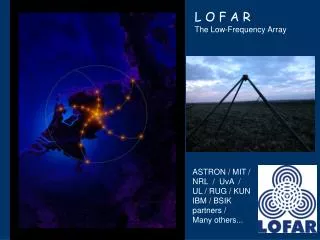
LOFAR The Low Frequency Array
LOFAR The Low Frequency Array. Shep Doeleman LOFAR Group. What is LOFAR?. Major new array for 10-240 MHz range 400 km across, fixed dipole receptors Fully digital, all-sky coverage, extreme agility Planned initial operation in 2006 Three-way collaboration ASTRON, in Dwingeloo, Netherlands

LOFAR The Low Frequency Array
E N D
Presentation Transcript
LOFARThe Low Frequency Array Shep Doeleman LOFAR Group
What is LOFAR? • Major new array for 10-240 MHz range • 400 km across, fixed dipole receptors • Fully digital, all-sky coverage, extreme agility • Planned initial operation in 2006 • Three-way collaboration • ASTRON, in Dwingeloo, Netherlands • Naval Research Lab (Remote Sensing Div.), Washington DC • MIT/Haystack
When and Where? • What is the timeline? • Target for initial operations – 2006 • Target for full operation – 2008 • Instrument lifetime – decades, with upgrades/refinements • Preliminary Design Review, June 3-5 • All systems except antennas and receiver • Delta-PDR scheduled for early September • Site selection • Three candidate sites: Netherlands, SW USA, W. Australia • Announcement of preferred site expected by September • Decision needed to permit focused design • Subsystem Critical Design Reviews • Second half of 2004 • System-level CDR in late 2004
SKA/LOFAR Common Challenges • Large Bitrates over long distances. • 10’s Tb/s over 1000’s km vs. 100’s Gb/s over 100’s km • x100 collecting areas from previous generation. • Use of phased arrays as stations. • Complex siting issues: large geographical area. • Wide science base: scale free configurations. • Large frequency range: will require multiple elements. • Calibration challenges: ionosphere, station beam • New direction dependent calibration formalism required • RFI mitigation, nulling. • Requires powerful central processor for analysis of full FOV. • New Scheduling Paradigm: multiple beams, subnetting, remote operation.
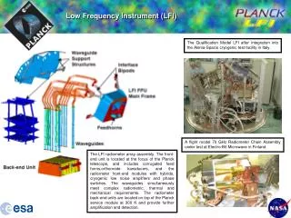
One LOFAR station, ~150 meters ~130 antennas generate 250 Gbit/sec Filtering and beamforming reduces this to ~2 Gbit/sec Outer 3/4 of stations create ~150 Gbits/sec aggregate Central core, 2km, ~3300 antennas Aggregate data rate ~ 6 Tbit/sec LOFAR: Overall layout Array layout Remote operations centers 400 km diameter
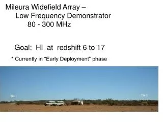
Scientific Versatility Redshifted HI from the Epoch of Reionization High-z starbursts Galaxy clusters and the IGM Cosmic ray distribution, and airshower radio bursts Steep spectrum and fossil radio galaxies Supernova remnants and ISM energy budget Interstellar recombination lines Nearby pulsars, ghost nebulae Extrasolar gas giant planetary radio emission Stellar flares Interstellar medium propagation effects Transients, GRB and LIGO event counterparts, buffering Solar radio studies CME detection, mapping by IPS, scattering Extremely high resolution ionospheric tomography Passive Ionospheric Radar Lane et al. (2001) Tozzi et al. (2000) Courtesy: B. Gaensler Courtesy: B. Jackson
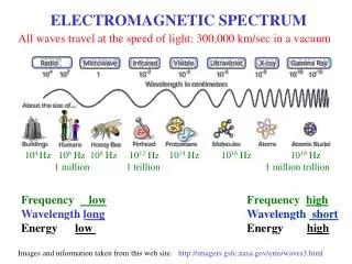
Low frequency antennas: 10-90MHz 1 sq. km. equiv. at 17MHz • Inverted-V shaped dipole • Electrically short design • Possible because sky noise dominates • Broadband • Simple, cheap, robust • Comes in 2 sizes, LBL and LBH
Prototyping • THETA (10 single polarized LBH elements) • Sky noise dominated in 40-80 MHz band
High Freq. Antenna Array:120-240MHz • Nominal 4x4 crossed dipole array • Electronic analog beamforming/steering • PC board switched delay lines (used before at 74 MHz) • Low cost is main challenge Single 4x4 unit Multiple units may be butted together for economy and performance
LOFAR Calibration • Maximize ratio of knowns/unknowns • Make lots of independent measurements • Know as much as possible about sky a priori • Know the instrument (e.g. response to environment) • Solve for smooth functions wherever possible • Gather a priori knowledge of ionosphere (e.g. GPS) • Bootstrapping approach to selfcal • Develop solutions for strong sources & subtract • Interpolate and improve coherence for weaker sources • Develop solutions for weaker sources & subtract • Fully position dependent across the Field of View “Peeling” – prototyping in progress
All Sky Monitor • Run 100% of time in the background • Make ~1000x1000 pixel map of sky every 0.5 sec • Full cross-correlation of 3200 antennas • 5.4 million baselines • Full field of view • Integrate on wide variety of timescales • Search for transient events, generate triggers • React to triggers • Re-point one or more LOFAR beams • Freeze and download the data buffer Huge discovery potential
WAN Implementation • Viable and affordable technologies identified • Requirement vary across array • Implementation matched to specific needs • Inexpensive, very high bandwidth for short-haul • Strong emphasis on mass-market components
Central Processor • ~1000 nodes in a 3D switching fabric • Bandwidth 2 Gbit/sec point-to-point
Central Processing Comparisons • In imaging mode, LOFAR requires ~40Tflops. • LOFAR CEP very flexible – calibration dominated. • Current LOFAR CEP cost: $16M. • SKA (Large N – Small D) requires ~ 10 Peta Flops • Difference of 10-12 years of Moore’s Law • But, LOFAR All Sky Monitor will achieve ~100Tflops and cost only $1M • So, targeted computation can be done at lower cost.
Summary • LOFAR is a complete ‘first step’ towards SKA. • May in some ways be more challenging than SKA. • Will offer lessons on useful timescales.