
Beam Diagnostic Boxes (REX)
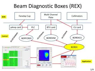
Beam Diagnostic Boxes (REX). Faraday Cup. Multi Channel Plate. Collimators. BDB. p Amp card. PLC. BTV card. CU card. cfv-170-borex. cfv-170-btvrex. Control. c fc-197-bisobeam. BOREXCU. BOREXIM. BOPFCREX. BOREX. Application. 1/4. Beam Diagnostic Boxes (HIE). Motor Movement.

Beam Diagnostic Boxes (REX)
E N D
Presentation Transcript
Beam Diagnostic Boxes (REX) Faraday Cup Multi Channel Plate Collimators BDB pAmp card PLC BTV card CU card cfv-170-borex cfv-170-btvrex Control cfc-197-bisobeam BOREXCU BOREXIM BOPFCREX BOREX Application 1/4
Beam Diagnostic Boxes (HIE) Motor Movement Long. Profile Time of Flight FC IN/OUT - Collimator Stripping Foil – Slit Silicon Detector Intensity Faraday Cup Silicon Detector BDB pAmp card ADC TDC TRIGSCAN card cfv-170-bdbrex2 cfv-170-bdbrex1 Control BOSILISO BOBDHIE 2/4
Main FESA Servers (HIE) #1 • BOBDHIE • Beam intensity acquisition (intensity[]) • Hardware settings (gain, voltage, trigger, gate..) • Collimator movement (as BOREX) • FC, Slit, Stripping foil, Silicon detector movement (new & as collimator) • Make a scan using slit and FC • Transverse profile and beam position (new acquisition property) {position[], intensity[]} • Settings (acq. freq., end position) • Command (start, stop, reset) • Planning 1sttest + Expert GUI : October 2014 3/4
Main FESA Servers (HIE) #2 • BOSILISO • Hardware settings • Time of flight • Acquisition of histogram per detector • X-axis corresponds to the number of charge ( energy) • Longitudinal profile measurement • Acquisition of histogram per detector • X-axis corresponds to the (arrival time – RF clock) • Post-processing (time of flight, energy peak..) to be done at the level of the OP application • Planning 1st test: To be defined 4/4


![[PDF] Free Download Curtains for Three By Rex Stout](https://cdn4.slideserve.com/8113618/slide1-dt.jpg)