Download
1 / 17
170 likes | 272 Views
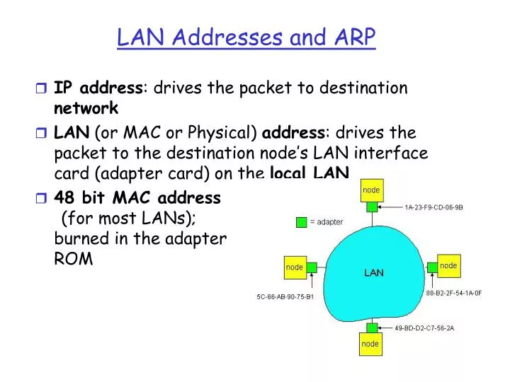
LAN Addresses and ARP. IP address : drives the packet to destination network LAN (or MAC or Physical) address : drives the packet to the destination node’s LAN interface card (adapter card) on the local LAN 48 bit MAC address (for most LANs); burned in the adapter ROM.

E N D
LAN Addresses and ARP • IP address: drives the packet to destination network • LAN (or MAC or Physical) address: drives the packet to the destination node’s LAN interface card (adapter card) on the local LAN • 48 bit MAC address(for most LANs); burned in the adapter ROM
Summary of MAC protocols • What do you do with a shared media? • Channel Partitioning, by time or frequency • Code Division MA, Wave Division MA • Random partitioning (dynamic), • ALOHA, S-ALOHA, CSMA, CSMA/CD • Taking Turns • polling from a central cite, token passing • For satellites, sensing if the channel is busy (if the channel is carrying a signal) is hard: ALOHA • For LANs, carrier sensing is easier, but no perfect): CSMA • Improve things is Collision Detection exists (CSMA/CD) • 802.3 (ethernet) is CSMA/CD
LAN Address (more) • MAC address allocation administered by IEEE • A manufacturer buys a portion of the address space (to assure uniqueness) • Analogy: (a) MAC address: like Social Security Number (b) IP address: like postal address • MAC flat address => portability • IP hierarchical address NOT portable (need mobile IP) • Broadcast LAN address: 1111………….1111
ARP: Address Resolution Protocol • Each IP node (Host, Router) on the LAN has ARP module and Table • ARP Table: IP/MAC address mappings for some LAN nodes < IP address; MAC address; TTL> < ………………………….. > • TTL (Time To Live): timer, typically 20 min
ARP (more) • Host A wants to send packet to destination IP addr XYZ on same LAN • Source Host first checks own ARP Table for IP addr XYZ • If XYZ not in the ARP Table, ARP module broadcasts ARP pkt: < XYZ, MAC (?) > • ALL nodes on the LAN accept and inspect the ARP pkt • Node XYZ responds with unicast ARP pkt carrying own MAC addr: < XYZ, MAC (XYZ) > • MAC address cached in ARP Table
Routing pkt to another LAN • Say, route packet from source IP addr <111.111.111.111> to destination addr <222.222.222.222> • In routing table at source Host, find router 111.111.111.110 • In ARP table at source, find MAC address E6-E9-00-17-BB-4B, etc
Ethernet • Widely deployed because: • Cheap as dirt! $20 for 100Mbs! • First LAN technology • Simpler and less expensive than token LANs and ATM • Kept up with the speed race: 10, 100, 1000 Mbps • Many E-net technologies (cable, fiber etc). But they all share common characteristics
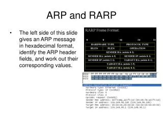
Ethernet Frame Structure • Sending adapter encapsulates an IP datagram (or other network layer protocol packet) in Ethernet Frame which contains a Preamble, a Header, Data, and CRC fields • Preamble: 7 bytes with the pattern 10101010 followed by one byte with the pattern 10101011; used for synchronizing receiver to sender clock (clocks are never exact, some drift is highly likely)
Ethernet Frame Structure (more) • Header contains Destination and Source Addresses and a Type field • Addresses: 6 bytes, frame is received by all adapters on a LAN and dropped if address does not match • Type: indicates the higher layer protocol, mostly IP but others may be supported such as Novell IPX and AppleTalk) • CRC: checked at receiver, if error is detected, the frame is simply dropped
Baseband Manchester Encoding • Baseband here means that no carrier is modulated; instead bits are encoded using Manchester encoding and transmitted directly by modified voltage of a DC signal • Manchester encoding ensures that a voltage transition occurs in each bit time which helps with receiver and sender clock synchronization
CSMA/CD A: sense channel, if idle then { transmit and monitor the channel; If detect another transmission then { abort and send jam signal; update # collisions; delay as required by exponential backoff algorithm; goto A } else {done with the frame; set collisions to zero} } else {wait until ongoing transmission is over and goto A}
CSMA/CD (more) • Jam Signal: to make sure all other transmitters are aware of the collision; 48 bits; • Exponential Backoff: • Goal is too adapt the offered rate by transmitters to the estimated current load (ie backoff when load is heavy) • After the first collision Choose K from {0,1}; delay is K x 512 bit transmission times • After second collision choose K from {0,1,2,3}… • After ten or more collisions, choose K from {0,1,2,3,4,…,1023}
CSMA/CD (more) • Note that under this scheme a new frame has a chance of sneaking in in the first attempt, even in heavy traffic • Ethernet Efficiency: under heavy traffic and large number of nodes: • (Does this help you at all?)
Ethernet Technologies: 10Base2 • 10==10Mbps; 2==under 200 meters maximum length of a cable segment; also referred to as “Cheapnet” • Uses thin coaxial cable in a bus topology • Repeaters are used to connect multiple segments (up to 5); a repeater repeats the bits it hears on one interface to its other interfaces, ie a physical layer device only!
10BaseT and 100BaseT • 10/100 Mbps rate; latter called “fast ethernet” • T stands for Twisted Pair • Hub to which nodes are connected by twisted pair, thus “star topology” • CSMA/CD implemented at the Hub
10BaseT and 100BaseT (more) • Max distance from node to Hub is 100 meters • Hub can disconnect a “jabbering adapter”; 10base2 would not work if an adapter does not stop transmitting on the cable • Hub can gather monitoring information and statistics for display to LAN administrators • 100BaseT does not use Manchester encoding; it uses 4B5B for better coding efficiency
Gbit Ethernet • Use standard Ethernet frame format • Allows for Point-to-point links and shared broadcast channels • In shared mode, CSMA/CD is used; short distances between nodes to be efficient • Uses Hubs called here “Buffered Distributors” • Full-Duplex at 1 Gbps for point-to-point links