Date Network Support
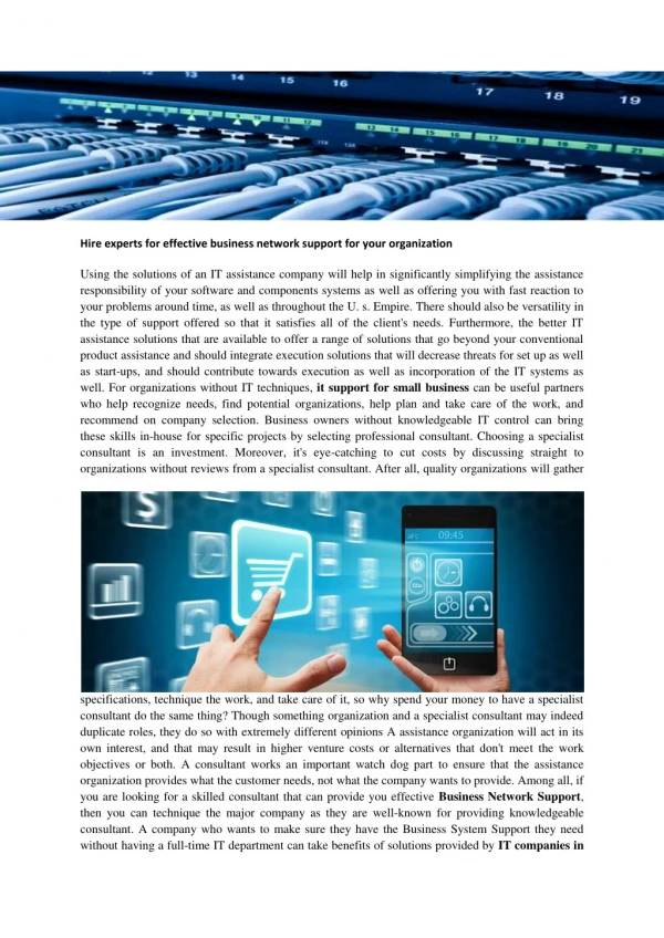
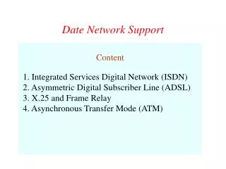
Date Network Support. Content 1. Integrated Services Digital Network (ISDN) 2. Asymmetric Digital Subscriber Line (ADSL) 3. X.25 and Frame Relay 4. Asynchronous Transfer Mode (ATM). ISDN User Network Interface. ISDN allows multiplexing of devices over single ISDN line Two interfaces

Date Network Support
E N D
Presentation Transcript
Date Network Support Content 1. Integrated Services Digital Network (ISDN) 2. Asymmetric Digital Subscriber Line (ADSL) 3. X.25 and Frame Relay 4. Asynchronous Transfer Mode (ATM)
ISDN User Network Interface • ISDN allows multiplexing of devices over single ISDN line • Two interfaces • Basic ISDN Interface • Primary ISDN Interface
Basic ISDN Interface (1) • Digital data exchanged between subscriber and NTE - Full Duplex • Separate physical line for each direction • Pseudoternary coding scheme • 1=no voltage, 0=positive or negative 750mV +/-10% • Data rate 192kbps • Basic access is two 64kbps B channels and one 16kbps D channel • This gives 144kbps multiplexed over 192kbps • Remaining capacity used for framing and sync
Basic ISDN Interface (2) • B channel is basic user channel • Data • PCM voice • Separate logical 64kbps connections for different destinations • D channel used for control or data • LAPD frames • Each frame 48 bits long • One frame every 250s
Primary ISDN • Point to point • Typically supporting PBX • 1.544Mbps • Based on US DS-1 • Used on T1 services • 23 B channels plus one D channel • Line coding is AMI using B8ZS • 2.048Mbps • Based on European standards • 30 B channels plus one D channel • Line coding is AMI using HDB3
Asymmetrical Digital Subscriber Line • ADSL • Link between subscriber and network • Local loop • Uses currently installed twisted pair cable • Can carry broader spectrum • 1 MHz or more
ADSL Design • Asymmetric • Greater capacity downstream than upstream • Frequency division multiplexing • Lowest 25kHz for voice • Plain old telephone service (POTS) • Use echo cancellation or FDM to give two bands • Use FDM within bands • Range 5.5km
Discrete Multitone • DMT • Multiple carrier signals at different frequencies • Some bits on each channel • 4kHz subchannels • Send test signal and use subchannels with better signal to noise ratio • 256 downstream subchannels at 4kHz (60kbps) • 15.36MHz • Impairments bring this down to 1.5Mbps to 9Mbps
Other Types of xDSL • High data rate DSL (HDSL) • Single line DSL (SDSL) • Very high data rate DSL (VDSL)
Advantages • Line efficiency • Single node to node link can be shared by many packets over time • Packets queued and transmitted as fast as possible • Data rate conversion • Each station connects to the local node at its own speed • Nodes buffer data if required to equalize rates • Packets are accepted even when network is busy • Delivery may slow down • Priorities can be used
Switching Technique • Station breaks long message into packets • Packets sent one at a time to the network • Packets handled in two ways • Datagram • Virtual circuit
Datagram • Each packet treated independently • Packets can take any practical route • Packets may arrive out of order • Packets may go missing • Up to receiver to re-order packets and recover from missing packets
Virtual Circuit • Preplanned route established before any packets sent • Call request and call accept packets establish connection (handshake) • Each packet contains a virtual circuit identifier instead of destination address • No routing decisions required for each packet • Clear request to drop circuit • Not a dedicated path
Virtual Circuit vs Datagram • Virtual circuits • Network can provide sequencing and error control • Packets are forwarded more quickly • No routing decisions to make • Less reliable • Loss of a node looses all circuits through that node • Datagram • No call setup phase • Better if few packets • More flexible • Routing can be used to avoid congested parts of the network
X.25 • 1976 • Interface between host and packet switched network • Almost universal on packet switched networks and packet switching in ISDN • Defines three layers • Physical • Link • Packet
X.25 - Physical • Interface between attached station and link to node • Data terminal equipment DTE (user equipment) • Data circuit terminating equipment DCE (node) • Reliable transfer across physical link • Sequence of frames
X.25 - Link • Link Access Protocol Balanced (LAPB) • Subset of HDLC (High-Level Data Link Control) X.25 - Packet • External virtual circuits • Logical connections (virtual circuits) between subscribers
Virtual Circuit Service • Virtual Call • Dynamically established virtual circuit • Permanent virtual circuit • Fixed network assigned virtual circuit
Frame Relay • Designed to be more efficient than X.25 • Developed before ATM • Larger installed base than ATM • ATM now of more interest on high speed networks
Frame Relay Background - X.25 • Call control packets, in band signaling • Multiplexing of virtual circuits at layer 3 • Layer 2 and 3 include flow and error control • Considerable overhead • Not appropriate for modern digital systems with high reliability
Frame Relay - Differences • Call control carried in separate logical connection • Multiplexing and switching at layer 2 • Eliminates one layer of processing • No hop by hop error or flow control • End to end flow and error control (if used) are done by higher layer • Single user data frame sent from source to destination and ACK (from higher layer) sent back
Advantages and Disadvantages • Lost link by link error and flow control • Increased reliability makes this less of a problem • Streamlined communications process • Lower delay • Higher throughput • ITU-T recommend frame relay above 2Mbps
Frame Relay - Virtual Circuits • Permanent virtual circuits (PVCs) • Original standard, more commonly used • Switched virtual circuits (SVCs) • Getting popular now
Permanent Virtual Circuits • Set up by a network operator • Defined as a connection between two sites • Fixed path, not to be set up on a call-by-call basis • Pre-configured by the provider or network manager with given bandwidth allocated packet-by-packet
Switched Virtual Circuits • Available by a call-by-call basis • User specifies a destination address similar to a phone number • Network dynamically establishes connections based on requests by many users • Network allocates bandwidth based on the user’s request
Asynchronous Transfer Mode (1) • Cell-based switching and multiplexing technology • Asynchronous; transmitted cells need not be periodic in times as in STM • General purpose: for a wide range of services: voice, packet data, video, imaging • Applied to both LAN and private network technologies
Asynchronous Transfer Mode (2) • Support both constant bit rate (CBR) or variable bit rate (VBR) • Each cell contains addresses information that establishes a virtual connection from source to destination • Support both permanent virtual connections or switched virtual connections (PVCs or SVCs) • Support multiple Quality of Service (QoS) classes for different applications on delay and loss performance
Multimedia Communications using ATM • Transmit text, voice, video, data traffic
ATM Cell • Fixed size cell 53 octets, 5-octet header and 48-octet payload (1 octet = 8 bits)
Protocol Architecture • Similarities between ATM and packet switching • Transfer of data in discrete chunks • Multiple logical connections over single physical interface • In ATM flow on each logical connection is in fixed sized packets called cells • Minimal error and flow control • Reduced overhead • Data rates (physical layer) 25.6Mbps to 622.08Mbps
Reference Model Planes • User plane • Provides for user information transfer • Control plane • Call and connection control • Management plane • Plane management • whole system functions • Layer management • Resources and parameters in protocol entities
ATM Logical Connections • Virtual channel connections (VCC) • Analogous to virtual circuit in X.25 • Basic unit of switching • Between two end users • Full duplex • Fixed size cells • Data, user-network exchange (control) and network-network exchange (network management and routing) • Virtual path connection (VPC) • Bundle of VCC with same end points
Advantages of Virtual Paths in ATM • Simplified network architecture • Increased network performance and reliability • Reduced processing • Short connection setup time • Enhanced network services
Summary of X.25, Frame Relay and ATM • X.25 • Widely used, inexpensive, but relatively slow • Frame Relay • Reliable, inexpensive, faster than X.25, able to handle heavy traffic in LAN • ATM • Fast, high bandwidth, high-capacity multimedia capabilities for voice, video and data communications
Main References • Data and Computer Communications, 6/e, by William Stallings, Prentice Hall. • ISDN and Broadband ISDN with Frame Relay and ATM, 4/e, by William Stallings, Prentice Hall. • eBusiness Essentials: Technology and Network Requirements for Mobile and Online Markets, 2/e, by Mark Norris and Steve West, John Wiley & Sons.