Download
1 / 32
320 likes | 374 Views
Explore principles of light interference, Michelson's Interferometer, and optical technology in this comprehensive guide. Learn about wavelengths, frequencies, and the process of interference. Discover how waves, whether light or sound, can reinforce or cancel each other, leading to constructive or destructive interference. Delve into the workings of Michelson's Interferometer and how it produces interference fringes. Gain insights into wave superposition and the concept of anti-reflection coating. Enhance your knowledge in the exciting field of optical technology and phenomena related to the interference of light waves.

E N D
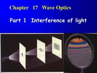
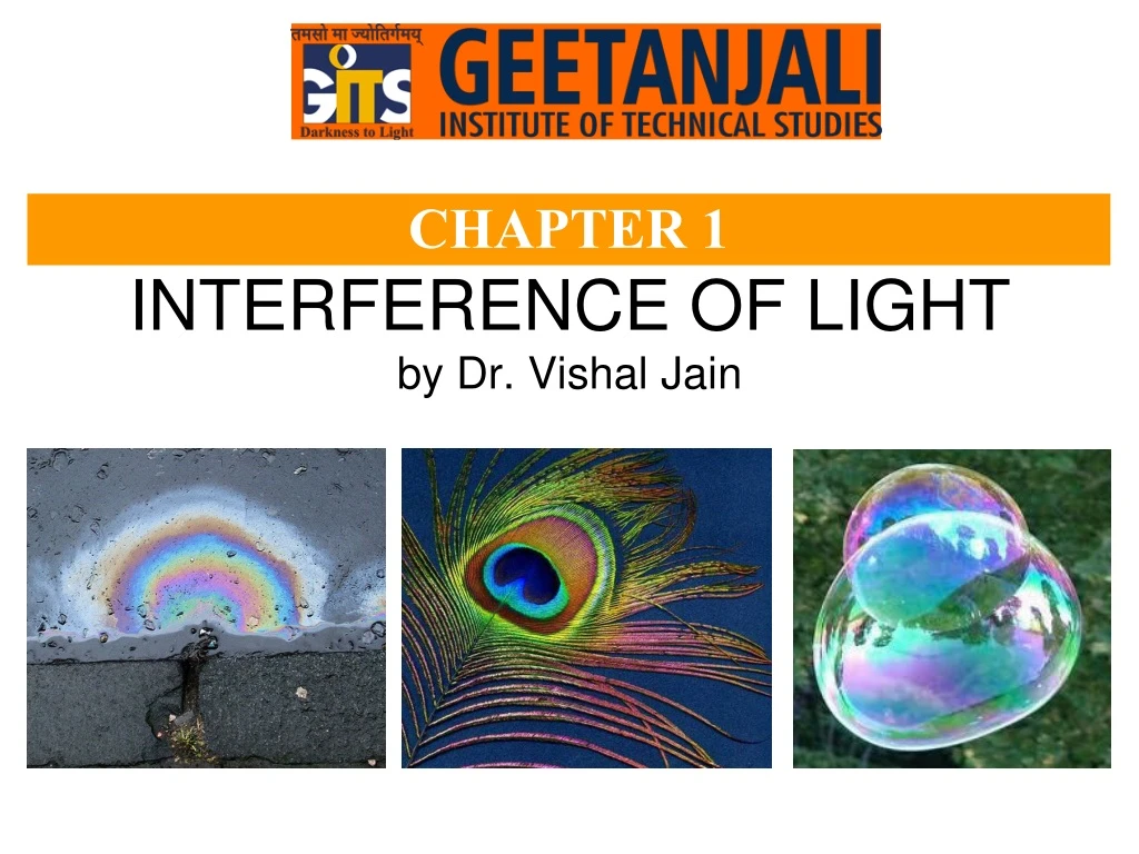
INTERFERENCE OF LIGHTby Dr. Vishal Jain CHAPTER 1
SyllabusPY-101 ENGINEERING PHYSICS CHAPTER 1 • Interference of light: • Michelson’s Interferometer: Production of circular & straight line fringes; Determination of wavelength of light; Determination of wavelength separation of two nearby wavelengths. • Optical technology: Elementary idea of anti-reflection coating and interference filters.
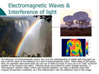
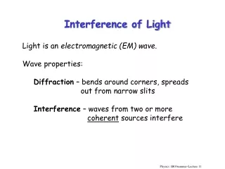
What is Light? Light is an electromagnetic radiation refers to visible regions of electromagnetic spectrum corresponding to the wavelength range of 400nm to 760nm which has transverse vibrations. Wave
General Definitions The Wavelength of a sin wave, λ, can be measured between any two points with the same phase, such as between crests, or troughs, as shown. The frequency, f, of a wave is the number of waves passing a point in a certain time. We normally use a time of one second, so this gives frequency the unit hertz (Hz), since one hertz is equal to one wave per second.
Principle of Superposition “Whenever two or more waves superimpose in a medium, the total displacement at any point is equal to the vector sum of individual displacement of waves at that point” If Y1, Y2, Y3…are different displacement vector due to the waves 1,2,3 …acting separately then according to the principle of superposition the resultant displacement is given by Y=Y1+Y2+Y3+……
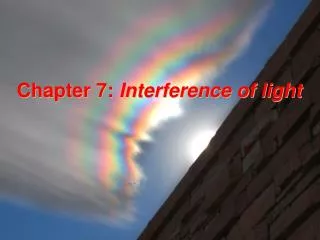
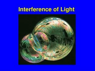
INTERFERENCE is the process in which two or more waves of the same frequency - be it light, sound, or other electromagnetic waves - either reinforce or cancel each other, the amplitude of the resulting wave being equal to the sum of the amplitudes of the combining waves. For example, if at a given instant in time and location along the medium, the crest of one wave meets the crest of a second wave, they will interfere in such a manner as to produce a "super-crest." Similarly, the interference of a trough and a trough interfere constructively to produce a "super-trough." This is called constructive interference. If the two amplitudes have opposite signs, they will subtract to form a combined wave with a lower amplitude. For example, the interaction of a crest with a trough is an example of destructive interference. Destructive interference has the tendency to decrease the resulting amount of displacement of the medium. The bright bands show constructive interference of light. The dark bands show destructive interference of light.
MICHELSON’S INTERFERROMETER The Michelson interferometer is a common configuration for optical interferometer and was invented by Albert Abraham Michelson in 1887. Using a beam splitter, a light source is split into two arms.
Principle:- The MI works on the principle of division of amplitude. When the incident beam of light falls on a beam splitter which divided light wave in two part in different directions. These two light beams after traveling different optical paths, are superimposed to each other and due to superposition interferences fringes formed.
Construction:- It consists of two highly polished plane mirror M1 and M2, with two optically plane glass plate G1 and G2 which are of same material and same thickness. The mirror M1 and M2 are adjusted in such a way that they are mutually perpendicular to each other. The plate G1 and G2 are exactly parallel to each other and placed at 45° to mirror M1 and M2. Plate G1 is half silvered from its back while G2 is plane and act as compensating plate. Plate G1 is known as beam-splitter plate. The mirror M2 with screw on its back can slightly titled about vertical and horizontal direction to make it exactly perpendicular to mirror M1. The mirror M1 can be moved forward or backward with the help of micrometer screw and this movement can be measured very accurately. Working: Light from a broad source is made paralied by using a convex lens L. Light from lens L is made to fall on glass plate G1 which is half silver polished from its back. This plate divides the incident beam into two light rays by the partial reflection and partial transmission, known as Beam splitter plate. The reflected ray travels towards mirror M1 and transmitted ray towards mirror M2. These rays after reflection from their respective mirrors meet again at 'O' and superpose to each other to produce interference fringes. This firings pattern is observed by using telescope.
Functioning of Compensating Plate: In absence of plate G2 the reflected ray passes the plate G1 twice, whereas the transmitted ray does not passes even once. Therefore, the optical paths of the two rays are not equal. To equalize this path the plate G2 which is exactly same as the plate G1 is introduced in path of the ray proceeding towards mirror M2 that is why this plate is called compensating plate because it compensate the additional path difference. Formation of fringes in MI
The shape of fringes in MI depends on inclination of mirror M1 and M2. Circular fringes are produced with monochromatic light, if the mirror M1 and M2 are perfectly perpendicular to each other. The virtual image of mirror M2 and the mirror M1 must be parallel. Therefore it is assumed that an imaginary air film is formed in between mirror M1 and virtual image mirror M'2. Therefore, the interference pattern will be obtained due to imaginary air film enclosed between M1 andM'2. From Fig. if the distance M1 and M2 and M'2is'd', the distance between S'1 and S'2 will be 2D. If the light ray coming from two virtual sources making an angle θ with the normal then the path difference between the two beams from S1 and S2 will becomes As one of the ray is reflecting from denser medium mirror M1, a path change of λ/2 occurs in it. Hence the effective path difference between them will be
If this path difference is equal to an integral number of wavelength λ, the condition for constructive interference is satisfied. Thus the bright fringe will formed. If this path difference is equal to an integral number of wavelength (2n±1)λ/2, the condition for destructive interference is satisfied. Thus the dark fringe will formed.
Radius of Fringes The Condition for maxima and minima in MI is given by For maxima For minima It is clear that on moving away from center the value of angle θ increases and the value of cosθ decreases hence the order of fringe also decrease so n maximum at center, The condition for nth dark ring at center is n-1 ……………Eq 1 n n-2 On moving m number of rings away from the center, the order of mth ring will be ( n-m). If mth ring make an angle θm with the axis of telescope then from equation n-m m rm ……………Eq 2 On Subtracting eq 1 and 2 …Eq 3 D θm Here …Eq 4
By eq 3 and 4 ……………Eq 5 ……………Eq 6 ……………Eq 7 ……………Eq 8 ……………Eq 9 ……………Eq 10 This equation gives the radius of mth ring
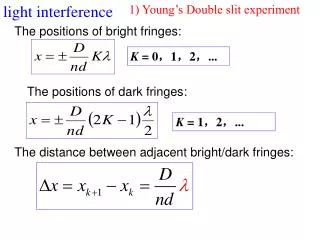
Applications of MI (1) Measurement of the wavelength of monochromatic light : The mirror M1 and M2 adjusted such that circular fringes are formed. For this purpose mirror M1 and M2 are made exactly perpendicular to each other. Now set the telescope at the center of fringe and move the mirror M1 in any direction, number of fringes shifted in field of view of telescope is counted. Let on moving mirror M1 through x distance number of fringes shifted is N So the path difference By using both equations we will calculate wavelength corresponding to distance and number of fringes shifted through telescope. (2) Determination of the difference in between two nearby wavelengths :- Suppose a source has two nearby wavelengths λ1 and λ2. Each wavelength gives rise its own fringe pattern in MI. By adjusting the position of the mirror M1, aposition will be found where fringes from both wavelength will coincide and form highly contrast fringes.
So the condition is given by When a mirror M1 has been moved through a certain distance, the bright fringe due to wavelength λ1 coincide with dark fringe due to wavelength λ2 and no fringe will be seen. On further movies mirror M1 the bright fringes again distinct, this is the position where n1+m order coincide with n2+m+1. So the condition given by Subtracting eq 2 by eq 1 So by eq 4 and 3 ……………Eq 1 ……………Eq 2 ……………Eq 3 ……………Eq 4
Problems & Solution Q.1. In MI 200 fringes cross the field of view when the movable mirror is displaced through 0.05896mm. Calculate the wavelength of the monochromatic light used. Solution:- Given N=200 x= 0.05896mm = 0.05896 X 10⁻³ m So the wavelength Å Q.2. The initial and final readings of MI screw are 10.7347 mm and 10.7057mm respectively, when 100 fringes pass trough the field of view. Calculate the wavelength of light used. Solution:- Given N=100 x=x2-x1= 10.7347-107057=0.029mm=0.029 X 10⁻³m So the wavelength Å
Problems & Solution Q.3. MI is set to form circular fringes with light of wavelength 5000Å. By Changing the path length of movable mirror slowly, 50 fringes cross the center of view How much path length has been changed? Solution:- Given N=50 λ= 5000 X 10-10m So the path length Q.4. In a Michelson Interferometer, when 200 fringes are shifted, the final reading of the screw was found to be 5.3675mm. If the wavelength of light was 5.92 X 10⁻⁷ m, What was the critical reading of the screw? Solution:- Given N=200 x=x2-x1= 5.3675 X10⁻³m - ? and wavelength λ = 5.92 X 10⁻²m So the wavelength Now initial reading of screw d1=d2 ± x = 5.3675 x 10⁻³m + 0.0592 x10⁻³m =5.4267 x 10⁻³m
Interference in Optical Technology Antireflection Coating:- In 1935, Smaulka discovered that reflection losses can be reduced by coating the surface with a thin transparent dielectric film known as antireflection coating. Principle:- The schematic diagram of a single layer antireflection coating is outline in Fig. 1. This coating consists of a layer of transparent material of thickness equal to one quarter the wavelength of the light in the coating material. The index of air and that of the optical part to be coated (µ2=(µ1µ3)1/2 for minimum reflection) . Reflection occurs at each surface of the coating. The two reflected waves are 180 degree out of phase and cancel through destructive interference; no energy, therefore, can appear in the reflected beam, and all the light is transmitted. n2=1.3 n1=1.0 n2=1.5 λ/4 Fig. 1. Antireflection coating Hence a film can acts as antireflection coating if it satisfies the following two conditions (1) Phase Condition, (2) Amplitude condition
From the fig 2. the optical path difference between ray 1 and ray 2 is (1) Phase Condition:- The wave reflected from the top and bottom surface of thin film should be in opposite phase so that they cancel each other due to destructive interference. It enable us to determine the required thickness of the thin film. Ray 1 Incident Ray Ray 2 • Here the first λ/2, is due to π phase change at air to film surface and the second λ/2 is due to π phase change at thin film/glass surface since both the reflection occurs from denser medium with respect to rare medium. • For normal incidence cos r = 1 Top Surface Air (µa) Film (µf) t Bottom Surface Glass (µg) • Addition of the λ in pat difference does not effect anything so Fig. 2. Antireflection coating • For destructive interference • For minimum thickness of thin film n=0
(1) Amplitude Condition:- The wave reflected from the top and bottom surface of thin film should have equal amplitude. Let the amplitude of reflected ray one and ray two are A1 and A2 respectively. A1=A2 • …………………….Eq 1 As the light is striking from air to thin film/glass boundaries. Suppose the refractive index’s of air, film and glass medium are μa, μf and μg respectively When a beam of light travel from one medium μ1 to another medium μ2, a part of light is reflected and the optical reflectivity of surface given by • …………………….Eq 2 • From the equation 1 and 2 the reflectivity • …….Eq 4 • ……..….Eq 3 • …….Eq 5 • For air µa=1 • ………….Eq 4 • …….Eq 6
Multilayer Antireflection Coating:- The construction and working of a dielectric coating used for partial and total reflection is shown in fig. The coating is composed of alternating layers of two transparent dielectric materials, one having a high index of refraction and another has lower index of refraction. Each layer has a thickness of λ/4 where λ is the wavelength of light in the appropriate layer and reflection occurs at each boundary between the two materials. When the direction of light travel is from a low index material to a high index material, there is a 180 degree phase change in the electric field of the reflected wave this occurs at surface 1, 3 and 5. So the wave reflected are 180 degree phase change. When light travels from higher refractive index material to lower one, there is no phase change in reflected wave.
Interference in Optical Technology Interference Filter :- An interference filter is an optical system that will transmit a very narrow range of wavelengths (monochromatic beam of light) Principle:- When parallel beam of light is incidence normally on a pair of plane parallel glass plate silvered on a inner surface and separated by a thin transparent film, then interference occurs for all wavelengths of white light and the maxima of different orders are formed in the transmitted light corresponding to wavelength given by For normal incidence, cos r = 1 Here t = Thickness of thin film separating the plate μ = Refractive index of transparent film
Construction and Working :- In an interference filter, a thin transparent film of MgF2 or Cryolite is placed between two semi reflective coating. When a beam of light is incident normally on the filter, multiple reflections take place within the film. The condition for maxima in transmitted light is given by Hence if the optical thickness µt of the film is integral multiple of half wavelength then the other wavelengths will be eliminated by destructive interference and λ, 2λ.. Will be transmitted through the filter without any obstructions. White Light Cover glass plate Transparent dielectric material Reflecting metal film Cover glass plate Monochromatic
If the angle of incidence is “i” , the wavelength of light passing through filter is given by ……………………………..[1] ……………………………..[2] by using Snell’s law ……………………………..[3] For n=1 ……………………………..[4] Here λ0=2μt Interference filter widely used in instrumentation for clinical chemistry, environment testing, colorimetric, elemental and laser line separation and fluorescence.
Problems & Solution Q.5. Find the reflectivity of a glass surface of refractive index 1.6 when a light beam is incident normally on it through the air. Solution:- Given µg=1.6 and µair= 1 So the optical reflectivity is given by Q.6. Consider an antireflection film of refractive index 1.38.Assume that its thickness is 9 X 10⁻⁶ cm. Calculate the wavelength in the visible region for which the film will be antireflection. Solution:- Given μf= 1.38 Thickness t= 9 X 10⁻⁶cm= 9 X 10⁻⁸m So the wavelength
Problems & Solution Q.7. Find the minimum thickness of a layer of magnesium florideμ = 1.38 required in an interference filter design to isolate light of wavelength 5893Å. How will peak transmittance change if the filter in tilled by 10 degree. Solution:- Given µmf=1.6 Wavelength = 5893 X 10-10m 2µt = nλ so for n=1 For 10 degree tilled filter When the filter is tilled, transmittance always changes towards shorter wavelength. Q.8. Two λ/4 thick layers are deposited on an opthalmic glass (μ =1.52) to reduce reflection loss. The first layer has refractive index (μ =1.38). Find the reflective index of the material of second layer. Solution:- Given µg=1.52, μ1 =1.38, μ2 =? We know that by using reflectivity amplitude condition µf= (1.38 X 1.52)1/2=1.448