
Simplified 3D Viewing Process: Triangles Rasterization & Interpolation
E N D
Presentation Transcript
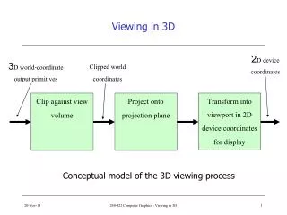
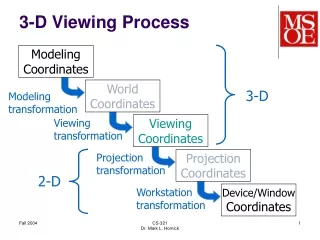
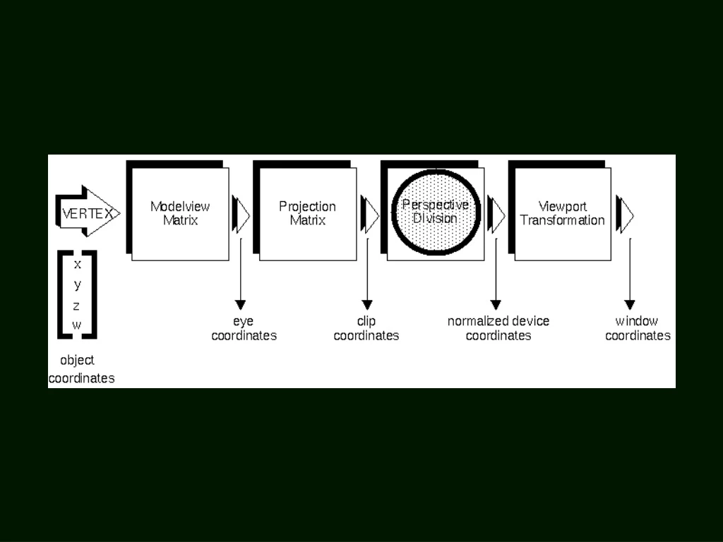
Model Space World Space View Space MC Model Transformation WC Viewing Transformation VC Projection Transformation Viewport Transformation DC PC Normalization & Clipping NC Projection Space Normalize Space Display Space 3D Viewing Process • 3D viewing process
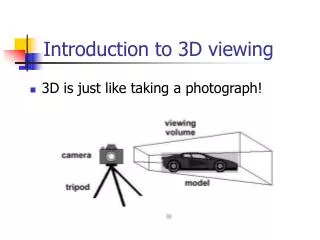
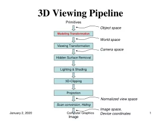
Simplified View • The Data Flow: 3D Polygons (+Colors, Lights, Normals, Texture Coordinates…etc.) • 2D Polygons • 2D Pixels (I.e., Output Images) Transform (& Lighting) Rasterization
Attributes Varying Transform (& Lighting) Rasterization fragment shader vertex shader vertex attributes: Color, Normal, Tex_coord, …etc. varying variables: interpolated from vertices to internal pixels
Key Questions • Q1: What screen pixels are covered by the triangles? • Q2: How to interpolate the attributes?
Triangles Only • We will discuss the rasterization of triangles only. • Why? • Polygon can be decomposed into triangles. • A triangle is always convex. • Results in algorithms that are more hardware friendly.
Being Hardware Friendly • [Angel 5e] Section 7.11.3 : • Intersect scan lines with polygon edges. • Sort the intersections, first by scan lines, then by order of x on each scan line. • It works for polygons in general, not just in triangles. • O(n log n) complexity feasible in software implementation only (i.e., not hardware friendly)
Using Edge Equations • Find the edge equations for P1-P2, P2-P3, P1-P3 • For each pixel, test which sides of the edges it is at. • Q: Do we need to test every pixel on the screen? P1 ege defined by Ax+By+c=0 P3 P2
Example P1 ege defined by Ax+By+C=0 P3 P2
Example • Now we have P1-P3 defined by 2x+y-4=0 • To test if a point (u,v) is inside the triangle, we calculate 2(u)+(v)-4. For example, (0,0) leads to 2(0)+(0)-4=-4 • So the negative side is inside. • Use P2 to decide which side is inside. • Negate A,B,C if you prefer the positive side P1 Ax+By+C=0 P3 P2
Color and Z • Now we know which pixels must be drawn. The next step is to find their colors and Z’s. • Gouraud shading: linear interpolation of the vertex colors. • Isn’t it straightforward? • Interpolate along the edges. (Y direction) • Then interpolate along the span. (X direction)
(255, 0, 0) (0, 0, 0) (0, 0, 0) Red (0, 0, 0) (255, 0, 0) Green (0, 0, 0) (0, 255, 0) (0, 0, 0) (0, 0, 255) (0, 255, 0) Blue (0, 0, 255) (0, 0, 0) Attribute Derivation • Color Interpolation
Interpolation OpenGL uses interpolation to find proper texels from specified texture coordinates
Perspectively Correct Interpolation • The previous slide is not “perspectively correct” • Consider the interpolation along the vertical (Y) direction. Should the checkers spaced equally? • Use the s to t conversion shown earlier, then you get the perspectively correct interpolation.
Interpolation in World Space vs Screen Space • P1=(x1, y1, z1, c1); P2=(x2, y2, z2, c2); P3=(x3, y3, z3, c3) in world space • If (x3, y3) = (1-t)(x1, y1) + t(x2, y2) then z3=(1-t)z1+t z2; c3=(1-t)c1+t c2 P1=(x1,y1,z1) P3=(x3,y3,z3) P2=(x2,y2,z2)
P1 P3 P2 Interpolation in World Space vs Screen Space • But, remember that we are interpolating on screen coordinates (x’, y’): y’ P’1 P’2 x’
Let P’1=(x’1, y’1); P’2=(x’2, y’2) and P’3=(x’3, y’3)= (1-s)(x’1, y’1) + s(x’2, y’2) • Does s=t? If not, should we compute z3 and c3 by s or t? • Express s in t (or vice versa), we get something like: • So, if we interpolate z on screen space, we get the z of some other point on the line • This is OK for Z’s, but may be a problem for texture coordinates (topic of another lecture)
Derivation of s and t • Two end points P1=(x1, y1, z1) and P2=(x2, y2, z2). Let P3=(1-t)P1+(t)P2 • After projection, P1, P2, P3 are projected to (x’1, y’1), (x’2, y’2), (x’3, y’3) in screen coordinates. Let (x’3, y’3)=(1-s)(x’1, y’1) + s(x’2, y’2).
(x’1, y’1), (x’2, y’2), (x’3, y’3) are obtained from P1, P2, P3 by:
Since We have:
When P3 is projected to the screen, we get (x’3, y’3) by dividing by w3, so: But remember that (x’3, y’3)=(1-s)(x’1, y’1) + s(x’2, y’2) Looking at x coordinate, we have
We may rewrite s in terms of t, w1, w2, x’1, and x’2. In fact, or conversely Surprisingly, x’1 and x’2 disappear.
Shadow • Loading 3D models directly from files • Three.js • Physically Based Rendering (PBR) See the gallery at: https://corona-renderer.com/gallery/