Download

1 / 51
510 likes | 671 Views
Introduction to 2D and 3D Computer Graphics. Introduction to Display Lists and 3D Viewing. Mastering 2D & 3D Graphics. Discuss Display Lists Benefits/Drawbacks of Segments vs. Structure models Think about what the ideal design would be... 3D Viewing: Coordinate Systems

E N D
Introduction to 2D and 3D Computer Graphics Introduction to Display Lists and 3D Viewing
Mastering 2D & 3D Graphics • Discuss Display Lists • Benefits/Drawbacks of Segments vs. Structure models • Think about what the ideal design would be... • 3D Viewing: • Coordinate Systems • Defining a “View Volume” • Benefits of mapping the view volume
Mastering 2D & 3D Graphics Display List Discussion • Display list models allow for • saving graphics objects or “elements” in memory for later use • allows for objects or “elements” to be copied, transformed, highlighted, referenced, modified, and displayed as many times as desired • “retains” data; once drawn the underlying graphics is not lost • can control the visibility of what gets displayed (called “regeneration”)
Mastering 2D & 3D Graphics Display List Discussion • Segments • provide for a “flat model” • where there are no relationships between segments • there can be 0-more segments, each containing one or many graphic objects • locks in the attribute settings, as attribute association is assumed to have been performed prior to segment storage (unless changed via the “inheritance filter”
Understanding Segments Introduction • Allows collections of graphic objects to be saved in memory... • Allows operations to be performed on entire segments • ...operations are NOT performed on individual objects ...this applies to visibility, copying, displaying, etc. • ...does not store functions or raster operations • ...drawing modes may be considered part of a graphic object’s definition
Understanding Segments Segment Attributes • Are not like primitive attributes • Apply to entire segments -- instead of individual graphic objects • Are applied on a "per-segment" basis • Allow each segment to have ONLY one set of segment attributes • Affect all graphic objects stored in a segment
Understanding Segments Segment Attributes • Allow applications to control... • ...the rendered appearance of a segment ...the picking properties of a segment • Affect the rendered appearance using... • ...highlighting ...visibility ...display priority ...segment transformation • Affect the picking properties using... • ...pick priority ...visibility ...detectability ...display priority
Understanding Segments Segment Display: regeneration • Is the process... • ...of drawing a picture on the screen, or ...of drawing a picture on plotter paper • ...called Segment Regeneration • Is the process of updating the displayed picture... • ...to accurately reflect the contents of segment storage
Understanding Segments Segment Display: regeneration • Clears the drawing surface... • ...and sends graphic objects from visible segments through the segment display path of the pipeline • Allows either explicit or implicit segment display... • ...via application invoked functions to draw segment • ...via implicit actions that require the display to be updated (i.e., implicitly regenerated)
Understanding Segments Segment Display: implicit regeneration • The picture may change when... • ...segment storage changes • ...segment attributes change • ...state list information changes • ...creating a segment • ...adding objects to a segment • ...deleting a segment • ...display priority or visibility, highlighting, segment transformation
Understanding Segments Segment Display: suppressed • With suppressed implicit regeneration... • ...changes that cause the picture to be altered (i.e., regenerated) DO NOT TAKE PLACE! • ...the drawn picture may NOT ACCURATELY reflect the contents of segment storage • one regeneration is performed at a later time • ...is an efficient way of making picture changes without updating the display with each change
Understanding Segments Segment Display: quick update methods • With UQUM implicit regeneration... ...changes that cause the picture to be altered (i.e., regenerated) use quick update methods ...simulated techniques efficiently reflect picture changes ...changes may not be a completely accurate representation of the requested picture • Allow the application to use implementation-dependent simulated methods for realizing changes without requiring the entire picture to be regenerated
Understanding Segments Segment Display: quick update methods • Are useful when segments are complex, large, or overlapping • Provides an alternative to time consuming screen updates; when supported, performance can be improved by using simulated methods • Are especially useful when interactively working with the display • Disadvantage: the picture may not look correct after a quick update method is used
Mastering 2D & 3D Graphics Display List Discussion • Structures • allow for hierarchical relationships to be built • stores “elements” (i.e., user requests) for primitives, attributes, and transformations • can be “called”, displayed (starting at any “base”) by “posting” • allows for groups of elements to be highlighted, set visible/invisible
Understanding Structures Introduction • Allows applications to define an object as a collection of hierarchically connected structures • Allows applications to use structures... • ...as building blocks of complex objects • for example, a wagon could be defined with five instances of a cube - one scaled flat and wide for the base, and four scaled short and wide for the sides
Understanding Structures Introduction • For common components, so they don't have to be duplicated but simply referenced • for example, logic gates used in a printed circuit board design program could be defined once and referenced as many times as needed • To closely follow an object's natural hierarchy • for example, a robot arm could consist of an upper arm, connected to a lower arm, which is connected to the hand; hierarchy allows for joints to move like a real arm!
Understanding Structures Frequently Used Terms • Centralized Structure Store... • ...is the workstation independent storage area for structure networks • Structures... • ...consist of a linear sequence of structure elements • Structure Elements... • ...are the smallest addressable unit, are formed from output primitives, attributes, labels, application data, transformations, and structure references
Understanding Structures Frequently Used Terms • Structure Network... • ...is a collection of structures arranged hierarchically • Structure Traversal... • ...processes a structure network, element by element, generating a displayed picture or changing state list values
Understanding Structures Frequently Used Terms • Child Structure... • ...is a structure that is invoked or referenced from within another structure; this is done by an execute structure function from within another structure • Descendant Structure... • ...is a child structure or a descendant of a child structure
Understanding Structures Structure Traversal • Structures are displayed... • ...by being traversed ...this causes elements stored in a structure network to flow along the remainder of the pipeline • Structures are displayed only on one or more requested workstations; they are never displayed on workstations that were not requested • To request display on a workstation... • ...a structure must be posted for display on that workstation
Understanding Structures Structure Traversal • To keep a structure or structure network from being ineligible for display on a specified workstation use... ...unpost structure • Unposting removes a structure or structure network from the list of roots posted to a particular workstation • One or all structures may be unposted at a time
Understanding Structures Structure Traversal • During traversal... • ...attribute elements apply to subsequent primitives within that structure and the primitives in any child structures ...this means that child structures inherit the attributes of their parents • ...this means that child structures pass on their current attributes on to their children • ...a child's attributes does not affect their parents
Understanding Structures Name Sets and Filters • Name sets and filters control groups of primitives using... • ...invisibility ...highlighting ...detectability • Name sets and filters provide great flexibility... • ...without requiring structure editing • ...without requiring you to know where the elements are within a structure • Invisibility filter specifies the name sets used to determine whether or not primitives are displayed when a structure is traversed
Understanding Structures Name Sets and Filters • Each filter consists of... • ...inclusion set of names, and • ...exclusion set of names • Primitives will be invisible, highlighted, or detectable, if they satisfy BOTH conditions: • 1) Belong to one or more classes in the inclusion set • 2) Does not belong to any classes in the exclusion set
Understanding Structures Dynamic Operations and Display Changes • The picture may require updating when... ...the contents of a structure changes (e.g., editing!) • ...a structure reference is changed • ...a structure is deleted • ...a structure is posted • ...a structure is unposted • ...or state list information is changed
Understanding Structures Dynamic Operations and Display Changes • Supports two modes to control when changes are dynamically updated... • ...deferral mode, and...modification mode • Deferral mode specifies when the display MUST be correct... • ...as soon as possible • ...before next interaction • ...at some time...when the application requests
Understanding Structures Dynamic Operations and Display Changes • Modification mode specifies the type of visual changes that should be done in the meantime if the display does not have to be correct now... • ...no immediate visual effect (like SUPPRESSED!) • ...update without regeneration (for immediate changes!) • ...use quick update methods (like UQUM!)
Structure Editing • Editing structures... • ...is similar to a text editor ...allows individual stored elements to be accessed • Editing operations include... • ...position the element pointer...insert elements ...replace elements ...delete elements • The element pointer determines where elements will be added or where editing will take place (like a current position)
Structure Editing Examples of Use • Inserting, deleting, replacing... • ...primitives -- can change the shape of a polygon, the meaning of a text string, delete an unwanted line • ...transformations -- can create animated effects, such as tumbling in 3D • ...attributes -- changes the color, line style, font, etc. • ...name set elements -- changes visibility, detectability, and highlighting • ...structure invocations -- allows change the topology of a structure network
Mastering 2D & 3D Graphics • Given what we have discussed • What would be the optimal design for display list storage for • Computer Animation? • Flight Simulator? • Is there a difference in the design based on the need for dynamic changes? • When is simple “picture capture” enough?
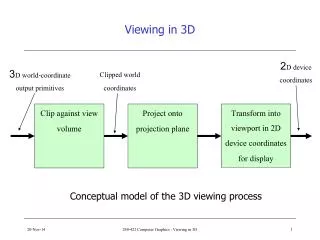
Mastering 2D & 3D Graphics • 3D Viewing: • Coordinate Systems • Defining a “View Volume” • Benefits of mapping the view volume
3D Viewing Transformations View Orientation Transformation • View orientation transformation... • ...defines the location and orientation of view reference coordinates relative to world coordinates • ...is specified by a view reference point, which is the origin of VRCs relative to WCs V Y View Reference Point X N U Z
3D Viewing Transformations View Orientation Transformation • View orientation transformation... • ...is specified by a point (called the view reference point) on a plane that is perpendicular to the N axis and by a vector (called the view plane normal) • ...where the view plane normal determines the N axis as a perpendicular distance from the view reference point • View Reference Point View Plane N axis: View Plane Normal
3D Viewing Transformations View Orientation Transformation • View orientation transformation... • ...is specified by a view up vector whose direction, projected onto the view plane, defines the V axis (specifying the vertical UP direction • ...think of it as projecting the view up vector along the view plane normal onto the view plane! V axis View up Vector • View Reference Point View Plane N axis: View Plane Normal
3D Viewing Transformations View Orientation Transformation • View orientation transformation... • ...defines the U axis as perpendicular to the V and N axes to form a right-handed coordinate system V axis View Plane View up Vector • VRP U axis N axis: View Plane Normal
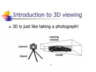
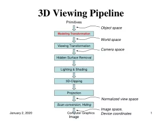
3D Viewing Transformations View Mapping Transformation • View mapping transformation... • ...defines the mapping of view reference coordinates to normalized projection coordinates • ...specifies a 3D volume of view reference coordinates to be mapped to a 3D volume of normalized projection coordinates (NPC)
3D Viewing Transformations View Mapping Transformation • The 3D volume in VRCs is called the view volume • The 3D volume in NPCs is called the projection viewport (0,1,0) Projection Viewport in NPCs View Volume in VRCs (0,0,1) (1,0,0)
3D Viewing Transformations View Volume • 3D view volumes are defined by... • ...a 2D view window that defines your field of view and provides the left and right, bottom and top extents of the view reference coordinates that you can see measured on the view plane V axis View Plane • VRP U axis N axis: View Plane Normal
3D Viewing Transformations View Volume • 3D view volumes are also defined by... • ...a view plane distance specifies where the view plane (an infinite plane perpendicular to the N axis where your picture is projected) intersects the N axis • ...the view plane distance displaces the VRP from the view plane N axis: View Plane Normal View Plane Distance • View Reference Point
3D Viewing Transformations View Volume • 3D view volumes are also defined by... • ...front and back plane distances, which are infinite planes perpendicular to the N axis Back Plane Distance View Plane Distance Back Plane Front Plane Distance View Plane N axis: View Plane Normal • View Reference Point Front Plane
3D Viewing Transformations View Volume • 3D view volumes are also defined by the projection type... • ...affects the shape of the view volume ...parallel or perspective • ...for parallel, the view volume is a parallelpiped • ...for perspective projections, the view volume is a truncated 4-slided pyramid
3D Viewing Transformations View Volume Back Plane Back Plane View Window (on the View Plane) VRP VRP • • Front Plane View Window (on the View Plane) Front Plane N axis: View Plane Normal N axis: View Plane Normal
3D Viewing Transformations View Volume • Lastly, 3D view volumes are also defined by the projection reference point...which • ...affects the shape of the view volume • ...is the center of projection for perspective projection Center of the Window V axis • View Plane • VRP • U axis Projection Reference Point N axis: View Plane Normal
3D Viewing Transformations View Volume • For parallel projections...the projection reference point... • ...specifies the direction of projection to be from the projection reference point to the center of the window V axis View Plane Center of the Window • • VRP • Projection Reference Point U axis N axis
3D Viewing Transformations View Volume for Perspective Projection • The view volume is the area between the front plane and the back plane as defined by the window and projection Back Plane View Plane View Window • Center of the Window V axis • VRP Front Plane U axis N axis View Volume • Projection Reference Point
3D Viewing Transformations View Volume for Parallel Projection • The view volume is the area between the front plane and the back plane as defined by the window and projection Back Plane View Plane View Window Center of the Window • V axis • VRP Front Plane • N axis U axis View Volume • Projection Reference Point
3D Viewing Transformations Parallel Projections • Oblique Parallel Projection: when the line connecting the projection reference point to the center of the window is not at right angles Front Plane Back Plane View Plane Projection Reference Point • (parallel) Center of the Window View Window Front Plane Back Plane View Plane Projection Reference Point • (oblique)
3D Viewing Transformations Perspective Projections • Oblique Perspective Projection: when the line connecting the projection reference point to the center of the window is not at right angles with the window Front Plane Back Plane View Plane Projection Reference Point • Center of the Window View Window • Projection Reference Point Front Plane Back Plane View Plane
3D Viewing Transformations Perspective Projections View Window Projection Reference Point • View Window Projection Reference Point •
3D Viewing Transformations Parallel Projections View Window Projection Reference Point • View Window Projection Reference Point •