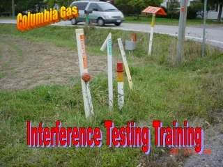
Interference Testing Training
Columbia Gas. Interference Testing Training. Agenda. In class training over PowerPoint Open discussion and review Lunch Hands on and field testing Follow up back in class room setting. Definition of Stray Current. Interference


Interference Testing Training
E N D
Presentation Transcript
Columbia Gas Interference Testing Training
Agenda • In class training over PowerPoint • Open discussion and review • Lunch • Hands on and field testing • Follow up back in class room setting
Definition of Stray Current Interference The National Association of Corrosion Engineers (NACE) recommended practice on cathodic protection underground structures provides several insights to the definition and evaluation of interference. Stray current is defined as “current through paths other than the intended circuit” or “the deterioration of a material, usually a metal that results from a reaction with its environment”.
Interference Objectives • Recognize • Test • Mitigate
Recognize • Pipe to soil potentials indication of possible interference situation • Areas of high voltage gradients or polarization • Structural effect of stray current pickup and discharge
Test • Basic survey measurements techniques • What are the minimum requirements? • Selection of testing equipment and materials • IR and Polarization measurements
Mitigate • Why mitigate? • Difficulties in interpreting data? • Selection and method of mitigation
Fundamental Review • Corrosion diminishes the integrity of the pipeline, increases the probability of pipeline failures and loss of system reliability. • Failure to properly analyze and arrest corrosion may result in loss of life and property, jeopardize pipeline integrity and corporate image, not to mention the economic forfeiture of pipeline system revenues.
Fundamental Review Continued This training session encompasses interference stray current, effect on pipeline polarization, recognition and role of voltage gradients, importance of the consideration of voltage drops, and understanding when stray current interference may result in corrosion.
Basic Faradays’ Law Rates of Metal Loss Fe (Iron) / STEEL 20LBs /Amp/ Year Al (Aluminum) 6.5 Cu (Copper) 45.7 Pb (Lead) 74.5 Mg (Magnesium) 8.8 Zn (Zinc) 23.6
Given: 1 amp of current discharging from a • pipeline for 1 year. • Metal loss: Approximately 20 lbs. • EQUIVALENT METAL LOSS • Equivalent Length • Pipe Diameter/W.T. Pipe Weight/Foot of Pipe Loss • 4” = 4.500” O.D. x 0.188 W.T 8.66 lbs/ft. 2.31 ft. • 6” = 6.625” O.D. x 0.280 W.T. 18.97 lbs/ft. 1.05 ft. • 10” = 10.750” O.D. x 0.188 W.T. 21.21 lbs/ft. 0.94 ft. • 16” = 16.000” O.D. x 0.250 W.T. 42.05 lbs/ft. 5.70 in. • 20” = 20.000” O.D. x 0.250 W.T. 52.73 lbs/ft. 4.55 in.
Stray Current cases can result in high Amp discharges, in which results to rapid corrosion or metal loss Remember the basic law of corrosion - For corrosion to occur all the components of a basic corrosion cell must be present.
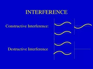
Conventional Current Flow Metallic connection Conventional current Flow - is the flow of current from positive to negative in a electrical circuit. Electron Flow Electrolyte Current Flow - needs to return to it’s original power source. Anode Cathode Electromotive Forceis the potential difference between the two structure. Positive Negative
Conventional Current Flow – Rectified System Anode bed Rectifier Unit Current Flow (+) Positive (+) Negative (-) Current Flow ( - ) Structure - Pipeline
Recognize Stray Current • Foreign structures nearby • other pipelines • buried tanks or petroleum facilities • Increase leakage in area • Readings increase more negative or positive (Annual monitoring, Bi-monthly inspections) • Corrosion focus on a pinpoint location onto structure • Coating disbondment near foreign line
Types of Interference There are two types of interference • Dynamic • Static
Dynamic Interference • Dynamic interference is recognized by pipe-to-soil measurements that fluctuate as a result of the source of stray current. These currents are continually varying in amplitude and/or continually, changing their electrolytic paths. • Light rail systems. • DC mining activities. • DC welding on the pipeline.
Two areas of discharge Dynamic Interference Example
Two Interference bonds connected Bond between pipeline and DC substation
Reverse Switch or Diodes Used • The rail system potential builds up positive • In prevention of shorting out company system with the return interference bond, in which bring the pipe line structure positive with the rail system, diodes are used
Static Interference • Static interference is a steady, continuous stray current source, such as, an impressed cathodic protection rectifier. • This session deals primarily with the definition, recognition, testing, and mitigation of static interference stray current.
Current returns through the soil Conventional Current Flow + Current Discharge – Corrosion - Current Discharge – Corrosion Static interference caused by a cathodic protection system
Conventional Current Flow Current Discharge – Corrosion Foreign Line Crossing and Stray Current Pickup and Discharge
Conventional Current Flow Current Discharge – Corrosion Current Discharge – Corrosion Testing non crossing foreign pipeline for stray current interference
Voltage Gradients • Remember the rectifier transformers, • The voltage gradient is build around the primary coils, energize a iron ore, which the secondary coils picks up the voltage potential and current flows through the circuit • Current still returns back • Stray current works in the same principal • When ever pipe passes through one of these voltage gradients from a foreign line, it picks up current
Ion Flow • Remember basic corrosion, electrons flow the opposite direction as current • At the cathode area (pick up), electrons will flow and build up to a negative potential • At the anode area (discharge location), loss of electrons builds up to a positive potential
Conventional Current Flow • Conventional current will flow, from positive to negative, • From the foreign ground bed system to the companies pipeline pickup area • Through the pipeline to the anode • From the anode (discharge area) to the foreign structure through the electrolyte
Interference Consideration Factors Impacting Corrosion Severity • Separation and routing of facilities • The location of the interfering current source • Magnitude and density of the current • Coating quality • Absence of external coating on the structures involved • Presence and location of mechanical joints of high electrical resistance
Interference Detection • When stray current interference is detected • Time is of the essence • Leakage can occur with in days or weeks
Effect of Interference Stray Current Pickup and Discharge Laws of Electricity and Interference Current • Current will always take the path of least resistance. • Stray current will always return to the source.
Effect of Interference Stray Current Pickup and Discharge Current Discharge May Only Reduce Polarization. • Where the stray current discharges, a detrimental affect will occur. • Pipe-to soil readings will be less negative. • May result in possible corrosion
Whether actual structural damage of corrosion occurs depends upon the existing level of cathodic polarization. If there is adequate polarization, current discharge may not cause metal loss. Potential shifts less negative are not necessarily indicative of interference corrosion
Electronic or Ionic When the stray current discharges, one of two reactions will occur. • If adequate polarization exists, the current discharge will result in an electronic exchange electrochemically. • No corrosion occurs. • Reduces the cathodic polarization.
Electronic or Ionic • When there is a lack of cathodic polarization present, the discharge of current will result in corrosion damage.
Foreign Stray Current Affect on Polarization • Stray current pickup increases polarization, this is represented by the higher,more negative, pipe-to-soil readings • Stray current discharge decreases polarization, this is represented by a more positive or less negative pipe-to-soil readings
IR drop information needed to use 100 mV shift Criteria or -.850 V polarization criteria
Pick Up and Discharge Areas • Need to identify areas of Pick up and Discharge • Pick up area, • More negative • Discharge area, • More Positive • Determine locations by CIS • Interrupting foreign structure • Data logger is the best tool to use
Connect Interrupter in series with the structure or ground cable. In this case, we used the structure cable.
Discharge Area • Indicated in CIS as the most positive potential reading • The area considered anodic • The area that will corrode • Faraday's law = 1amp = 20lb’s per yr • Most likely found at the point of crossing or the maximum exposure to the foreign line • The location for the bond to be established
Graph of Stray Current Pickup and Discharge on Bare Pipeline
Graph of Stray Current Pickup and Discharge on Coated Pipeline
Pipe-to-Soil Readings Through Foreign Influence and Resultant Depression in Potentials
Rules of Thumb - Interference Testing • Current will always take the path of least resistance. • Current must always return to its source. • Get the “big picture” of all metallic structures and possible stray current sources, and.
Interference Testing Rules of Thumb • Follow the data if practical by finding the corresponding stray current discharge point when a stray current pickup is found. • Simplest test is to measure the metallic voltage shifts.