Understanding Network Layers and Protocols for Efficient Data Delivery
Learn about the network layer in computer systems, its role in routing data packets, packet-switched networks, datagram networks, and virtual-circuit networks. Explore how routing tables work and the differences between datagram and virtual-circuit networks.


Understanding Network Layers and Protocols for Efficient Data Delivery
E N D
Presentation Transcript
Kingdom of Saudi Arabia • Prince Norah bint Abdul Rahman University • College of Computer Since and Information System • NET331 Network layer(1) T.NajahAlSubaie
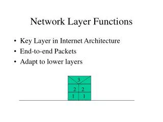
Introduction • The physical and data link layers of a network operate locally. • These two layers are jointly responsible for data delivery on the network from one node to the next.
Need for Network Layer • To solve the problem of delivery through several links, the network layer was designed. • The network layer is responsible for host-to-host delivery and for routing the packets through the routers.
Need for Network Layer • The network layer at the router is responsible for routing the packet. • When a packet arrives, the router consults its routing table and finds the link from which the packet must be sent. • The packet, after some changes in the header, with the routing information is passed to the data link layer again. • The network layer at the destination is responsible for address verification; it makes sure that the destination address on the packet is the same as the address of the host.
Internet as a Datagram Network • The Internet, at the network layer, is a packet switched network. • In the packet-switched network, the message needs to be divided into packets of fixed or variable size. • The size of the packet is determined by the network and the governing protocol. • When a switch receives a packet, no matter what is the source or destination, the packet must wait if there are other packets being processed.
Packet Switching Networks • Packet switching uses either the virtual circuit approach or the datagram approach.
Datagram Networks • In a datagram network, each packet is treated independently of all others. Even if a packet is part of a multi packet transmission, the network treats it as though it existed alone. • Packets in this approach are referred to as datagrams.
Routing Table • In this type of network, each switch has a routing table which is based on the destination address. • The routing tables are dynamic and are updated periodically. • The destination addresses and the corresponding forwarding output ports are recorded in the tables.
Destination Address • Every packet in a datagram network carries a header that contains, among other information, the destination address of the packet. • When the switch receives the packet, this destination address is examined; the routing table is consulted to find the corresponding port through which the packet should be forwarded. • This address remains the same during the entire journey of the packet.
VIRTUAL-CIRCUIT NETWORKS • a source and destination need to go through three phases: setup, data transfer, and teardown. • In the setup phase, the source and destination use their global addresses to help switches make table entries for the connection. • In the teardown phase, the source and destination inform the switches to delete the corresponding entry. • Data transfer occurs between these two phases
Source-to-destination data transfer in a virtual-circuit network
VIRTUAL-CIRCUIT NETWORKS • Setup Phase: • In the setup phase, a switch creates an entry for a virtual circuit. • Data Transfer Phase: • All switches need to have a table entry for this virtual circuit. The table, has four columns for each virtual circuit that is already set up. • Teardowil Phase: • In this phase, source A, after sending all frames to B, sends a special frame called a teardown request. • Destination B responds with a teardown confirmation frame. • All switches delete the corresponding entry from their tables.
Datagram VS. Virtual circuit networks • Efficiency • In datagram network, resources are allocated only when there are packets to be transferred. • In virtual-circuit network, all packets belonging to the same source and destination travel the same path; • Delay: • In datagram network, each packet may experience a wait at a switch before it is forwarded. In addition, the delay is not uniform for the packets of a message. • In a virtual-circuit network, there is a one-time delay for setup and a one-time delay for teardown. If resources are allocated during the setup phase, there is no wait time for individual packets.
Network Layer: Internet Protocol • In the Internet model, the main network protocol is the Internet Protocol (IP) • The Internet Protocol version 4 (IPv4) is the delivery mechanism used by the TCP/IP protocols.
IPv4 • IPv4 is an unreliable and connectionless datagram protocol-a best-effort delivery service. • The term best-effort means that IPv4 provides no error control or flow control(except for error detection on the header). • IPv4 assumes the unreliability of the underlying layers and does its best to get a transmission through to its destination, but with no guarantees.
IPv4 • IPv4 is also a connectionless protocol for a packet switching network that uses the datagram approach. • This means that each datagram is handled independently, and each datagram can follow a different route to the destination. • This implies that datagrams sent by the same source to the same destination could arrive out of order. Also, some could be lost or corrupted during transmission. • IPv4 relies on a higher-level protocol to take care of all these problems.
IPv4 datagram format • A datagram is a variable-length packet consisting of two parts: header and data. • The header is 20 to 60 bytes in length and contains information essential to routing. • Source address. This 32-bit field defines the IPv4 address of the source. • This field must remain unchanged during the time the IPv4 datagram travels from the source host to the destination host. • Destination address. This 32-bit field defines the IPv4 address of the destination. • This field must remain unchanged during the time the IPv4 datagram travels from the source host to the destination host.
IPv4 datagram format • Version (VER). This 4-bit field defines the version of the IPv4 protocol. • Header length (HLEN). This 4-bit field defines the total length of the datagram header in 4-byte words. • Services: an 8-bit field called as service type • The first 3 bits are called precedence bits. • The precedence defines the priority of the datagram in issues such as congestion. • If a router is congested and needs to discard some datagrams, those datagrams with lowest precedence are discarded first. • The next 4 bits are called type of service (TOS) bits,
IPv4 datagram format • TOS bits is a 4-bit subfield with each bit having a special meaning. • A bit can be either 0 or 1, and only one of the bits can have the value of 1 in each datagram • Identification. This field is used in fragmentation
Service Type Default types of service
IPv4 datagram format • Total length:This is a n-bit field that defines the total length (header plus data) of the IPv4 datagram in bytes. • To find the length of the data coming from the upper layer, subtract the header length from the total length. • The header length can be found by multiplying the value in the HLEN field by 4