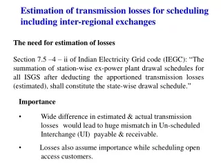
Investigation of losses for MKI FVC system
Investigation of losses for MKI FVC system. TE-ABT-EC. Contents. Introduction Objectives Measurements Tests and Results PCB Design Conclusion. Self introduction. Electronics and programming Hiking Skiing. BTEC National Diploma Higher National Diploma Bachelor of Engineering

Investigation of losses for MKI FVC system
E N D
Presentation Transcript
Contents Introduction Objectives Measurements Tests and Results PCB Design Conclusion
Self introduction • Electronics and programming • Hiking • Skiing • BTEC National Diploma • Higher National Diploma • Bachelor of Engineering • Master’s Degree in Engineering • Summer job at the town Hall of Seynod • Technician at Pfeiffer Vacuum Annecy • Internship at CERN Refuge du Parmelan 4
Receiver FVC Thyratron tank filled with dielectric oil Faraday cage Emitter Bias board 25m Introduction 120cm Thyratron Grids System overview Plastic Optical Fibre • PLC system • Grid voltage reading • SCADA • Data logging • Trending FVC: Frequency to Voltage Converter System is designed for : • Thyratron health check • Premature ageing detection • Thyratron readiness • Preventive maintenance • Additional MKI protection (Interlocks)
FVC Introduction Th D PFN PFN Th M Th M Th D Th M Th M PFN PFN Th D Th D <25m <25m • MKI injection system at point 2 and point 8 • 8 thyratrons HV switches • 8 Plastic fibre links • Maximum length around 25 meters ≥25m ≥ 25m Thyratron Control racks MS Tank ≈ 25 meters DS Tank LHC MKI injection system at point 2 LHC MKI injection system topology at point 2
Introduction CX1171 thyratron schematic diagram Optical emitter High voltage thyratron gas tube • Grid voltage to frequency converter • Power supply for thyratron heaters/reservoirs • Supply for thyratron grid voltages Thyratron bias board
Introduction • Trend from WinCC SCADA system of injection kicker • Problems: • 3 measurements are faulty • 1 measurement on the limit (noisy) Thyratron grid voltages acquisition at point 2
Faraday cage Receiver FVC Emitter Bias board Oscilloscope 25/50/100m 120cm Objectives Dummy Load Oscilloscope Optokon Thyratron bias board FVC Dummy Load Tank optical fibreconnector: POF: MKI FVC test bench synoptic Signal losses investigation Repeater box design Alternative solutions
Optical budget calculation PT(min): Minimum coupled power of transmitter (dBm) PRL, min: Sensitivity of the receiver (dBm) Il: Sum of insertion loss of feed-throughs (dB) OPM: Optical power margin, which accounts for LED degradation, supply voltage variation, etc.(dB) α(max): Maximum attenuation of fibre (dB/m) Theoretical length higher than the actual configuration
Measurements ↕∆d Gap between the emitter coupling and the fibre Fibre Distance vs attenuation chart Avago SFH756V transmitter
Measurements taken at point 2 (UA23) • Optokon instrument used to measure optical power in µW • The optical power was found to be reduced by a factor of 7 to 9 timesless than expected • Hypothetically, losses could be localised inside the thyratron tank OPTOKON OFT 820-POF
Splicing and polishing investigations • Usage of USB microscope for surface magnification • Cutting tool without polishing • Fibre polishing and optimisation Termination surface finely polished (Zoom x210) Difference: 0.75 dB Termination surface spliced by the tool (Zoom x210) RENNSTEIG 8000 0001 3 Termination surface polished (Zoom x210)
Alternative Fibre Advantages: • Step Index HCS usable at 650 and 850nm with the actual emitter/receiver • Glass optical fibre has lower attenuation and greater BW than POF (≤6dB/km) at 850nm • Superior Macro bending performance http://www.ieee802.org/3/NGAUTO/public/jan17/whelan_3NGAUTO_01b_0117.pdf • Improvement of optical fibre quality (200μm HCS Fibre)
Tank filled with oil Receiver FVC Faraday cage Emitter Bias board ≥25m Repeater Design 120cm Load ≥ 1m • As intermediary solution adding a repeater between thyratron optical output and acquisition system Repeater
Conclusion Avago SFH756V Not Recommended for New Design Avago AFBR-X528CZ Repeaters implemented Possible components replacement with new versions for future installations Long-term test of the transmitter in oil (cold and warm oil)