Download
1 / 33
690 likes | 2.18k Views
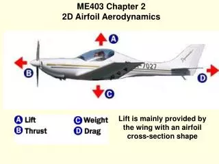
ME403 Chapter 2 2D Airfoil Aerodynamics. Lift is mainly provided by the wing with an airfoil cross-section shape. Airfoil Geometry. An airfoil is the 2D cross-section shape of the wing, which creates sufficient lift with minimal drag. Historical Airfoils. Historical Airfoils.

E N D
ME403 Chapter 2 2D Airfoil Aerodynamics Lift is mainly provided by the wing with an airfoil cross-section shape
Airfoil Geometry An airfoil is the 2D cross-section shape of the wing, which creates sufficient lift with minimal drag
Typical Streamlines Angle of Attack
Pressure Coefficient Distribution In free-stream: At stagnation point (V=0): Positive Cp means the pressure is higher than the free-stream (atmospheric) pressure, and negative Cp means suction relative to free-stream pressure. The maximum, which occurs at the stagnation point, is always 1.
Viscous Boundary Layer Velocity profile creates skin friction (shear) drag on surface
Flat Plate Skin Friction Drag Coefficient Curve fit formula for turbulent boundary layer (Re > 500,000):
Evolution of Airfoil Design Laminar boundary layer creates less skin friction drag
Boundary Layer Flow Separation When flow separation occurs, there is also pressure drag.
Pressure (Form) Drag due to Flow Separation 100% Pressure Drag Total Profile Drag = Skin Friction Drag + Form Drag
Center of Pressure The resultant aerodynamic force acts at the Center of Pressure (c.p.), about which the moment is zero.
NACA Airfoils and Test Data 4-Digit Series 5-Digit Series 6 Series
Wind Tunnel Tests Force transducer behind model senses lift, drag and pitching moment directly. Motor-controlled mechanism adjusts the model’s angle of attack.
Wing Section Models Model for measuring lift, drag and pitching moment Model for measuring surface pressure distribution
NACA 0006 Data at Re = 3,180,000 There is a maximum Lift-to-Drag ratio (L/D). Location of Center of Pressure (c.p.) varies with a
NACA 2312 Data at Re = 3,120,000 Lift decreases and drag increases sharply beyond the stall (max. Cl) point, due to boundary layer separation.
Aerodynamic Center Since the c.p. varies with a, it is more desirable to use a fixed Aerodynamic Center (a.c.) as the point of action of the lift and drag. The pitching moment about this point can be calculated, and is found insensitive to a. For most airfoils, the a.c. locates at around quarter chord (x=c/4). Pitching Moment Coefficient:
Typical Non-Cambered AirfoilLift Curve & Drag PolarNACA 0006
Airfoil Generator at http://www.ae.su.oz.au/aero/info/index.html
Airfoil Analysis Code at http://www.ae.su.oz.au/aero/info/index.html