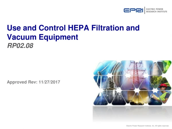
Use and Control HEPA Filtration and Vacuum Equipment RP02.08
590 likes | 861 Views
Use and Control HEPA Filtration and Vacuum Equipment RP02.08. Approved Rev : 11/27/2017. Standardized Task Evaluation Program.

Use and Control HEPA Filtration and Vacuum Equipment RP02.08
E N D
Presentation Transcript
Use and Control HEPA Filtration and Vacuum EquipmentRP02.08 Approved Rev: 11/27/2017
Standardized Task Evaluation Program The Standardized Task Evaluation (STE) program promotes a work-ready workforce through the standardization of common tasks by defining the knowledge and skills required to perform a given task. Subject Matter Experts (SMEs) analyze the task and generate lesson plans, knowledge examination, and performance evaluation elements. These elements are combined to create an STE package. The Electric Power Research Institute (EPRI) facilitates the development, oversees the quality, and programmatically implements each STE. EPRI STE members have access to these materials and permission to implement these STEs in accordance with their site training and qualification procedures.
Guidance for Completing this Module • Duration of this Computer-Based Training course is approximately 2 to 3 hours. • Material for this presentation is primarily derived from the NISPs; and in particular, NISP-RP-08, Use and Control HEPA Filtration and Vacuum Equipment. Various industry references have also been used in the development of this presentation. Note that HEPA is an acronym for High Efficiency Particulate Air. • This training is objective-based. Brown-colored text at the top of a slide designates an objective with related material on the given slide. • Feedback on this presentation should be provided to EPRI and STPNOC. Send email to: tmstroschein@stpegs.com. • After viewing this presentation, be sure to complete the associated 25-question, multiple choice exam. Passing score is 80% or better.
10CFR20, Subpart B, Radiation Protection Program Important Point • §20.1101(b) - The licensee shall use, to the extent practical, procedures and engineering controls based upon sound radiation protection principles to achieve occupational doses and doses to members of the public that are as low as reasonably achievable (ALARA).
Use and Control HEPA Filtration and Vacuum EquipmentOverview • Efficiency Bulletin (EB) 17-01, Portable Supplemental Radiation Protection Technician Training and Qualification directed: • Development and implementation of Nuclear Industry Standard Processes (NISPs) to standardize RP procedures for supplemental workforce. • Creation of standardized, portable RP qualifications for the supplemental workforce. • Overall goals of EB 17-01 are to: • Eliminate site-specific qualifications of supplemental radiation protection technicians through development of a standard vendor training program. • Significantly reduce or eliminate the time each site historically spends to qualify the supplemental RP technicians (SRPTs) prior to the start of an outage or project. • Additionally, this will result in improved SRPT performance due to standardization of key radiation protection processes and procedures. • “Use and Control HEPA Filtration and Vacuum Equipment” is one of these standardized processes and uses NISP-RP-08, titled Use and Control HEPA Filtration and Vacuum Equipment as the primary reference.
Use and Control HEPA Filtration and Vacuum Equipment Overview • In addition to reviewing this presentation, you should also read the associated procedure, NISP-RP-08, in its entirety. This presentation largely follows the procedure as it is written. • Clarifying notes are provided in Section 4 of the procedure and are numerically referenced – as a superscript – at the end of certain sentences within the procedure. • You should note in the procedure, the process diagram which provides overall direction.
Terminal Objective • When working as an RP technician at a U.S. nuclear utility, the individual will be able to properly select, setup, periodically monitor and store HEPA-outfitted equipment in order to support worker activities in a radiological control area in accordance with the standards of NISP-RP-08, Use and Control HEPA Filtration and Vacuum Equipment.
Enabling Objectives • Describe the general requirements for set-up, use and control of HEPA and vacuum units. • Select equipment and hose size by using capture velocity chart or historical data (as appropriate), or as specified in the RWP or ALARA plan. • Describe conditions that would require the need for: • HEPA Filter • Charcoal Filter • Spark Arrestor • Wet Vacuum • Describe how to verify efficiency testing of the HEPA equipment is current. • State the types of vacuum or ventilation units that are approved for use in the RCA. • Describe the steps and precautions in the set-up of HEPA equipment. • Describe the correct assembly of HEPA ventilation or vacuum equipment.
Enabling Objectives • Describe the proper location for a charcoal filter. • Explain the actions to be taken if the operation of HEPA ventilation or vacuum equipment is not as expected. • Describe the purpose of HEPA/Vacuum Issue and Return Log (NISP-RP-08, Attachment 3). • Describe actions and considerations for monitoring the operation of HEPA vacuums and ventilation, including potential for changing conditions such as dose rates of accumulated filtered material. • Describe the purpose of HEPA Shift/Daily Inspection Log (NISP-RP-08, Attachment 4). • Describe the use of continuous air monitors for high risk activities (i.e. steam generators ventilation) to provide a quick indication of HEPA equipment failure. • Describe storage requirements for HEPA equipment, including proper storage of charcoal filters to prevent damage from moisture.
Use and Control HEPA Filtration and Vacuum Equipment • General Requirements • Selection of HEPA Equipment • HEPA Setup • Monitoring of HEPA Operation • Storage of HEPA Equipment
Describe the general requirements for set-up, use and control of HEPA and vacuum units. • In the procedure, note the general requirements which include: • Only HEPA and vacuum units with a current DOP/PAO test can be used to control airborne radioactivity. • HEPA and vacuum units shall be DOP/PAO tested based on the manufacturer recommendations but as a minimum will be tested once every 24 months or when HEPA filter media is changed. Date for retesting will be displayed on the unit. • Only HEPA certified vacuum units can be used inside the RCA. • Physical inspection is required for all HEPA and vacuum units prior to being placed in service. Specific attention is to be made to electrical connects and power cords, hoses and connections, and equipment guards. Do not operate any equipment with potential safety defects. • All HEPA and vacuum units used inside the RCA must be tagged as internally contaminated and cannot be opened without Radiation Protection oversight. If the unit has been used in an alpha Level 3 area it must be indicated on the tag as possibly containing alpha contamination. • Contact Industrial Safety prior to using a HEPA ventilation unit any time that volatile substances, vapors or fumes are expected to be generated during the work activity. 1 • Portable HEPA ventilation does NOT eliminate the requirements for air quality or confined space monitoring. • Only those vacuums labeled as wet vacuums, or wet/dry vacuums or systems designed for this purpose, shall be used to remove liquids.
Describe the general requirements for set-up, use and control of HEPA and vacuum units. • In the procedure, note the general requirements which include: • HEPAs that require an operating voltage greater than 120V AC will require maintenance support for electrical connections. HEPA’s requiring multi-phase wiring (e.g., 480V, 3-phase) should have proper rotation checked prior to placing the unit into service • All HEPA units and vacuums used in the RCA, while not in use, will be controlled in a manner to prevent unauthorized removal and use. • When not in the use, the openings of the HEPA ventilation unit and hoses will be covered to prevent access to any potentially contaminated surface or component. • An Out of Service tag will be attached to any HEPA ventilation or vacuum unit removed from service due to equipment failure or retesting due date. • Radiation levels should be monitored on the HEPA units and vacuums while they are in service. Where available, and based on the potential for increase in radiation levels, telemetry units should be placed on the filter housing to provide a continuous method of monitoring. • Fire zone loading should be considered when installing HEPA equipment. • Spark arrestors shall be used on all HEPA units for work activities that generate sparks such as grinding on metal. 2 • Do NOT operate HEPA units with the end of the suction hose covered as this will damage components, over heat the unit, and may result in fire. • Site guidance should be utilized for the removal and replacement of HEPA filters based on unit type and model available.
Use and Control HEPA Filtration and Vacuum Equipment • General Requirements • Selection of HEPA Equipment • HEPA Setup • Monitoring of HEPA Operation • Storage of HEPA Equipment
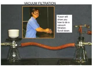
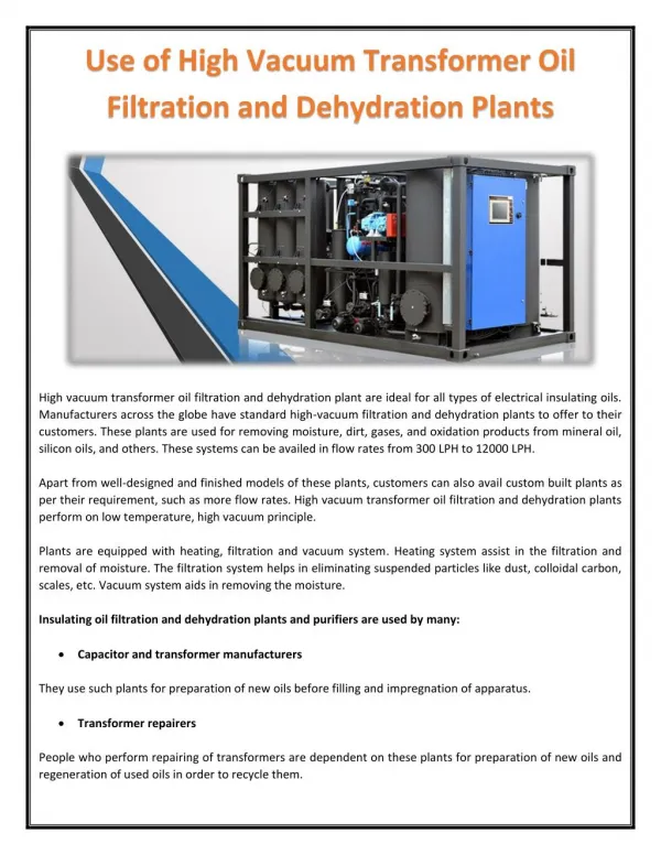
Portable HEPA Ventilation Units Purpose • HEPA ventilation units are used frequently as an engineering control to minimize the spread of airborne radioactivity. • Through the use of HEPA ventilation units, the use of respirators can be eliminated for many jobs. • HEPA ventilation units also help control the spread of contamination during jobs involving high contamination levels.
Selection of HEPA and Vacuum Equipment • The decision to use HEPA ventilation or vacuum equipment, and the type required, will be made based on the work activity and the expected radiological conditions and the implementing instructions will be included in the RWP or ALARA plan. • Prior to determining the proper engineering controls the potential airborne activity will be projected during the TEDE ALARA process used by the station. The potential airborne generation takes into consideration the work methods being used, plant ventilation systems, and environmental conditions (e.g. wet surfaces). Once the airborne generation rate has been projected the proper equipment can be selected.
Select equipment and hose size by using capture velocity chart or historical data (as appropriate), or as specified in the RWP or ALARA plan. • Unless site specific information is provided, use Attachment 1, Capture Velocity Chart, to determine the capture velocity needed based on the work activity. If the work activity has been completed successfully in the past then historical information can be used to determine the capture velocity requirements. • Unless site specific information is provided, use Attachment 2, Effective Capture Velocity and Distance Chart, to determine the ventilation hose size requirements for the work activity.
Select equipment and hose size by using capture velocity chart or historical data (as appropriate), or as specified in the RWP or ALARA plan. • In order to use these charts, it is important to understand a few items: • Capture velocity is the minimum air velocity required to overcome the motion of airborne particulates (or gases) and accelerate them into the capturing airstream. • If the capture velocity is not adequate for the contamination generated, capture of the contaminants will not occur. • If the hose face is moved away from the work, the ability to capture contamination is seriously compromised. • Capture velocity needed for the ‘contaminant’ (particulate or gas) is measured in Feet Per Minute (FPM). Capture velocity is also based on the manner in which the contaminant is intended to be dispersed. • Flow rate (or capacity, or size) of ventilation equipment (that is, the blower or fan) is provided in Cubic Feet per Minute (CFM).
Select equipment and hose size by using capture velocity chart or historical data (as appropriate), or as specified in the RWP or ALARA plan. • We will now work through an example using Attachment 1, Capture Velocity Chart, and Attachment 2, Effective Capture Velocity and Distance Chart, to determine the needed ventilation equipment for the work activity. • Problem statement: You will need to provide HEPA ventilation equipment for a welding job that will use a welding spray booth. The hose of the equipment will only be allowed to be 9” away from the work. The ventilation hose that you have available is 6” in diameter. Determine the flow rate needed for the blower (or fan) for this work.
Select equipment and hose size by using capture velocity chart or historical data (as appropriate), or as specified in the RWP or ALARA plan. • Solution: • If not provided, you will first need to estimate the capture velocity (in feet per minute, or FPM). Using the capture velocity chart in the procedure (Attachment 1), we estimate that a capture velocity of 150 FPM will be needed (see next slide). • Then, using the Effective Capture Velocity and Distance chart for a 6” hose in the procedure (Attachment 2), and knowing that the hose will be 9” away from the work, we enter the column for @ 9” (see following slide). • We need a capture velocity of 150 FPM. Going down the column we are looking for a minimum capture velocity of 150 FPM. We see that this is achieved with a blower (or fan) rated with a flow rate of 900 CFM (leftmost column) – which can achieve a capture velocity of 155 FPM. See the following slide. If you do not have a 900 CFM rated blower or fan – you will then want to use the next larger size, likely a 1000 CFM rated blower, which will still provide at least 150 FPM capture velocity.
Describe conditions that would require the need for: HEPA Filter, Charcoal Filter, Spark Arrestor, Wet Vacuum • Select the proper ventilation equipment by taking into consideration the following additional factors: • Weight loading of the equipment on floor or grating • Ability to position the hose at the required distance to provide proper capture velocity and allow the workers the visibility to perform the task. • Spark arrestors should be installed for all spark producing work activities. Consider the use of fire resistant hose material if available. • Consider the use of a noise suppressor on the discharge of the unit to facilitate a better work environment. • Select the proper vacuum unit depending on the following conditions • Wet or dry conditions are expected during the work process • Distance the material will have to be transported through the hose from the suction point to the receptacle. • Potential dose rates on the material being vacuumed
Describe conditions that would require the need for: HEPA Filter, Charcoal Filter, Spark Arrestor, Wet Vacuum • In applications where iodine gas is expected, charcoal filters should be considered / utilized. 3 • If a charcoal filter bank is being used take additional steps to monitor for iodine at the discharge of the unit. Several factors contribute to the charcoals ability to remove iodine including humidity which can change over the course of a work activity.
State the types of vacuum or ventilation units that are approved for use in the RCA. • Only HEPA certified vacuum units can be used inside the RCA. • All HEPA units and vacuums used in the RCA, while not in use, will be controlled in a manner to prevent unauthorized removal and use. • When not in the use, the openings of the HEPA ventilation unit and hoses will be covered to prevent access to any potentially contaminated surface or component.
Use and Control HEPA Filtration and Vacuum Equipment • General Requirements • Selection of HEPA Equipment • HEPA Setup • Monitoring of HEPA Operation • Storage of HEPA Equipment
Describe how to verify efficiency testing of the HEPA equipment is current. • HEPA and vacuum units shall be DOP/PAO tested based on the manufacturer recommendations but as a minimum will be tested once every 24 months or when HEPA filter media is changed. Date for retesting will be displayed on the unit.
Describe the steps and precautions in the set-up of HEPA equipment. • Verify the HEPA or vacuum unit DOP/PAO testing is current prior to setup in the field. • Verify the tamper proof seal or equivalent is in place on the unit. • Validate the current radiological conditions of the unit are indicated on the RAM label or tag. • Check the physical condition of the unit including the condition of the power cord. Do not plug into an electrical power source if the cord shows signs of damage. • Each HEPA and vacuum unit shall have a unique numbering system and should be signed out to the work location using Attachment 3, HEPA/Vacuum Issue and Return Log, or electronically using site specific processes. • Use caution when removing end covers of hoses or HEPA units due to the potential for internal contamination. Proper contamination control measures should be implemented prior to removing the covers.
Describe the steps and precautions in the set-up of HEPA equipment. • Ensure exhaust of the HEPA unit is directed away from a contamination area boundary to prevent the potential for airborne generation. • Ensure the HEPA exhaust screen is intact which prevents personnel injury from rotating equipment. • Use the following guidance to route the ventilation hose • Minimize the amount of hose used to prevent the potential collapsing of the trunk. Keep the hose as straight as possible from the unit to the work site • Make sure the suction of the hose is located in the proper location to provide the capture velocity necessary to provide the proper ventilation • Minimize sharp bends or curves which can reduce the suction flow and prevent the desired CFM from being achieved. If sharp bends are necessary consider the use of fabricated joints. • Route hose in low traffic areas or in the overhead to prevent trip hazards to personnel. As appropriate use safety flagging to make personnel aware of the hazard. • If the hose is being routed vertically consider the need for hose supports based on the weight of the HEPA hose being used
Describe the steps and precautions in the set-up of HEPA equipment. • After inspection and installation of the HEPA hose, connect the unit to power source. If the unit uses greater than 120V AC the unit must be connected by a qualified individual. • Power up the unit and observe the magnehelic gauge, if equipped, and ensure it falls within the band established for that unit. If the magnehelic gauge is outside the band then secure the unit and take the following actions • Validate the hose did not collapse while the unit was in operation. • Validate the magnehelic gauge connections are not loose • The end of the hose is open and free • There are no sharp bends in the hose which could reduce the air flow • If no issues where found during a-c above consider the need to replace the HEPA and/or Pre-filters using site guidance. • For units operating on 3 phase 220/480V AC it may be necessary to verify the rotation of the unit upon initial startup. • For operation of vacuum units individuals should review the requirements in Attachment 5, Worker Instructions for Vacuum Operation.
Describe the correct assembly of HEPA ventilation or vacuum equipment. • In general, the preferred order of assembly for HEPA-outfitted equipment is for the HEPA filter to be placed upstream of any installed charcoal filter. The reason for this is allow for removal of particulate material before it reaches the charcoal filter – this eliminates unwanted ‘loading’ of the since the charcoal filter is intended to predominantly remove gaseous iodine. • A spark arrestor, if used, is to be installed at the open end of the suction line to prevent any sparks from entering the ventilation equipment.
Describe the correct assembly of HEPA ventilation or vacuum equipment. • Additionally, it is preferred that both the HEPA and charcoal filters be located in the suction line; that is, upstream of the blower or fan. • The reason for this to ensure ‘capture’ of the contaminant due to the negative pressure created by the blower or fan. • If the HEPA and / or charcoal filter were to be located in the exhaust line (that is, downstream of the blower or fan) – then a hole in the hose or line between the blower or fan, and the filter would allow some or all of the contaminant to be dispersed without being captured by the filter(s).
Describe the correct assembly of HEPA ventilation or vacuum equipment. Charcoal Filter (if used) needs to go here, or blower exhaust routed to plant filtration equipment. HEPA Filter Blower or Fan Pre-filter (if used) Air Flow Duct or Hose Spark Arrestor Magnehelic Gauge
Clarifying Notes • At some sites the discharge of the HEPA units may be directed towards, or attached directly to, the plant’s containment purge or ventilation system. Ensure the equipment is installed according to site specific documents and tested as required prior to use. • Note that in such instances, the intent is to utilized the plant’s permanently installed contaminant filtration equipment.
Clarifying Notes • HEPA ventilation equipment could transport harmful vapors or fumes to other areas of the plant or the HEPA media could be damaged. Ensure a proper safety evaluation has been completed prior to using HEPA ventilation equipment when other industrial hazards are present. • Due to the flow of oxygen a fire in a ventilation hose can spread rapidly. Ensure proper precautions are taken if spark producing work is taking place in the area.
Describe the proper location for a charcoal filter. • If a charcoal filter is required install the device in the suction of the HEPA unit or per the manufacturer’s instructions.
Use and Control HEPA Filtration and Vacuum Equipment • General Requirements • Selection of HEPA Equipment • HEPA Setup • Monitoring of HEPA Operation • Storage of HEPA Equipment
Describe actions and considerations for monitoring the operation of HEPA vacuums and ventilation, including potential for changing conditions such as dose rates of accumulated filtered material. • Dose rates monitoring frequency for HEPA and vacuum units should be based on the potential for changing conditions. In most cases the units should be checked daily when in use or at a survey frequency determined by RP supervision. Survey frequency is documented on attachment 4. • Consider installing a telemetry device, if available, and there is the potential for the HEPA or vacuum unit to become a source of exposure. Install the monitoring device on the inlet of the filter assembly. • Use Attachment 4, HEPA Shift/Daily Inspection, to validate the operation of the unit once per Day/Shift or at the frequency determined by RP supervision while in operation.
Explain the actions to be taken if the operation of HEPA ventilation or vacuum equipment is not as expected. • If equipment or conditions are not as expected: • Stop work until the issue or question can be resolved. • Note that specific guidance is provided in Attachment 5 of the procedure for workers using vacuum equipment. These should be briefed to the worker prior to the start of the job.
Attachment 5 – Worker Instructions for Vacuum Operation • If at any time you are uncertain about your responsibilities, place work in a safe condition and immediately contact RP for guidance. • Only use a vacuum unit that has been DOP/PAO tested within the last 24 months • Do NOT open a vacuum unit without contacting RP. • Do not use the vacuum for any other job or task than the one for which the vacuum was issued. • Do not use wet vacuums for dry work or dry vacuums for wet work • If a dry vacuum inadvertently collects liquids, then stop work, shut off unit and contact RP. • Ensure that the vacuum cleaner and associated equipment has a yellow radioactive material label or tag with dose rate information. If the tag is not attached, contact RP prior to use for surveying. • If you have reason to believe that dose rates or contamination levels on the vacuum cleaner or attachments have changed during use, then contact RP to perform a radiological survey and update the radioactive material label or tag • Verify the unit has a tamper proof seal or equivalent installed and is intact. • Cover the openings on the suction lines after use, or between uses, to prevent release of contamination. • Immediately discontinue the use of vacuum cleaner(s) that do not perform properly, have safety issues, or appear to be leaking or discharging at any location other than the normal discharge port. • If the vacuum becomes full and needs to be emptied, then contact RP • Return vacuum cleaner to issue station when no longer needed.
Describe the purpose of HEPA/Vacuum Issue and Return Log (NISP-RP-08, Attachment 3). • This log is used to identify the location of the equipment so that the unit can be checked or surveyed.
Describe the purpose of HEPA Shift/Daily Inspection Log (NISP-RP-08, Attachment 4). • This log is used to validate that the equipment is continuing to operate properly.
Describe the use of continuous air monitors for high risk activities (i.e. steam generators ventilation) to provide a quick indication of HEPA equipment failure. • The effectiveness of HEPA unit operation should be monitored based on the risk associated with failure of the unit. • For high risk activities (for example, Steam generators ventilation) consider the use of continuous air monitors to provide a quick indication of equipment failure. • For other medium to low risk activities smear the discharge of the unit and/or obtain air samples to validate the units operation.
Use and Control HEPA Filtration and Vacuum Equipment • General Requirements • Selection of HEPA Equipment • HEPA Setup • Monitoring of HEPA Operation • Storage of HEPA Equipment
Describe storage requirements for HEPA equipment, including proper storage of charcoal filters to prevent damage from moisture. • HEPA and Vacuum equipment should be stored in a controlled manner to prevent unauthorized personnel from placing equipment in service. • RP personnel will maintain the control of HEPA and vacuum units by issuing equipment using Attachment 3, HEPA/Vacuum Issue/Return Log, or site electronic processes or forms. • Fire loading should be considered before storing HEPA ventilation equipment inside the plant. • HEPA and vacuum equipment shall be clearly tagged in accordance with NISP-RP-04, Radiological Posting and Labeling. • Charcoal filtration units should be stored to prevent damage from moisture based on manufactures recommendations.