Download
1 / 24
280 likes | 768 Views
Bulk MEMS 2013, Part 1 sami.franssila@aalto.fi. Types of MEMS. Bulk MEMS: anisotropic wet or DRIE of bulk silicon SOI MEMS: DRIE or wet silicon etching Surface MEMS: thin films on top of a wafer Integrated MEMS: CMOS and MEMS on same chip. Through-wafer nozzles.

E N D
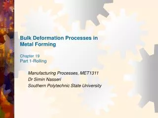
Bulk MEMS 2013, Part 1 sami.franssila@aalto.fi
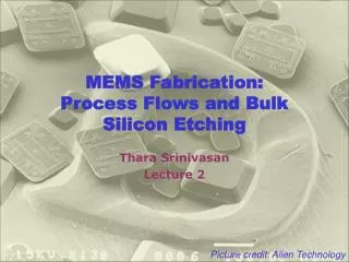
Types of MEMS Bulk MEMS: anisotropic wet or DRIE of bulk silicon SOI MEMS: DRIE or wet silicon etching Surface MEMS: thin films on top of a wafer Integrated MEMS: CMOS and MEMS on same chip
Through-wafer nozzles Basic design relies on silicon anisotropic etching and wafer thickness accuracy. Only squares and rectangles possible. Advanced design uses p++ etch stop structure to accurately define the nozzle, and non-critical etching to make the large structure. Any shape can be made.
Mask #1 Mask #2 c a b d Critical vs. non-critical masks
Two sides of the wafer Double sided Single sided Furnaces, oxidation Sputtering Furnaces, CVD Evaporation/MBE Furnaces, PECVD Ion implantation Furnaces, diffusion PECVD Furnaces, annealing Lithography Wet etching and cleaning in a tank CVD epitaxy Spray processing CMP Barrel plasma etching/stripping RIE/plasma etching Resist stripping in a tank Spin processing
Batch vs. single wafer Batch reactor: -many wafers -both sides processed Single wafer reactor: -one wafer -one side processed
a b Peeling mask Fig. 21.17 Also known as nested mask Figure 20.4
a b c DRIE holes thru-wafer Things to consider: -mask material ? (hard mask needed !) -alignment of top and bottom structures ? -which side to etch first ? -is film on other side removed ? -what is the aspect ratio that can be etched ? -what wall thickness is strong enough ?
Exercise 1: DRIE holes Explain step-by-step how the structure is made. This kind og assignment calls for chronological sequence of steps, so simple and unambiguos that you can leave the actual processing to be done by somebody else. If a standard process is used, it is enough to say ”lithography”, or ”thermal oxidation” but if something special is involved, then you have to clarify. It is always good to think about dimensions and thicknessess, and most often they are demanded, too.
a b c DRIE hole process • 0. Thin wafer, 380 µm • Thermal oxidation • Litho on top surface, defines wall thickness • Oxide RIE & resist strip • Litho on backside, defines tube inner diameter; critical alignment • Backside oxide RIE & resist strip • DRIE of silicon from back, 300 µm • DRIE from top side, 150 µm
Exercise 2: microthruster Explain the fabrication steps: Things to consider: -two wafers bonded, how ? -top wafer requires double side processing -clearly KOH/TMAH wet etching is used, but what is the mask material ?
Thruster • 0. <100> DSP silicon wafer Top wafer • Thermal oxidation • Litho on top side • Oxide RIE & resist strip • Litho on bottom • Oxide RIE & strip • KOH etching • Thermal oxidation Bottom wafer • Litho for diffused resistor • Oxide etch & strip • Resistor diffusion • Oxide etching in HF • Thermal oxidation • Litho • Oxide RIE & resist strip • KOH etching Bonding: Fusion bonding (=direct bonding)
Membrane formation Nitride membrane; no timing needed Timed silicon membrane; thickness depends on etch rate and wafer thickness control. Thin membrane thickness control bad. SOI wafer, membrane thickness determined by SOI device layer thickness
Piezoresistive pressure sensor Boron doped p++ membrane is a passive structure ! Active elements consist of the deposited polysilicon resistors.
Pt measurement electrodes sensor material oxide Nitride Pt heater Micro hot plate: nitride membrane
sensor material Pt measurement electrodes oxide Nitride Pt heater Exercise 3: micro hot plate • 0. Double side polished <100> wafer • LPCVD nitride • Litho on backside • Nitride RIE & resist strip • Pt sputter • Litho • Pt etch & strip • CVD oxide • Litho • Oxide etch & strip • Pt sputter • Litho • Pt etch & resist strip • Frontside protection (jig) • Backside KOH etch • Sensor material deposition
AFM tips: thru-wafer (2) SOI wafer with 5-μm thick device layer thermal oxidation LPCVD nitride etch nitride from front side lithography for the tip etch oxide etch silicon isotropically (+ resist strip) thermal oxidation for tip-sharpening lithography to define the cantilever DRIE of device silicon (+resist strip) thermal oxidation for passivation lithography for piezoresistors boron implantation for resistors (+strip) lithography & etch for contact boron implantation for contacts (+ strip) implant activation in RTA aluminum deposition and patterning Front protection: polyimide spinning backside nitride litho & etch & strip backside TMAH anisotropic etch buried oxide etching polyimide plasma removal
BAW resonator Left as homework exercise.