Download
1 / 31
310 likes | 454 Views
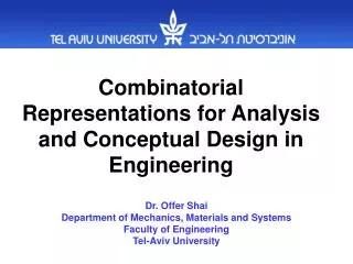
Dr. Shai from the Department of Mechanics, Materials and Systems at Tel-Aviv University explores the transformative power of graph representations in engineering design. The talk outlines innovative processes for converting concepts from kinematic systems to static systems through dual graph representations. A detailed example will illustrate the creation of a new theoretical concept, focusing on the development of an active torque amplifier. Conclusions will touch on the implications for future research and the computerization of engineering systems, showcasing how graph theory can redefine problem-solving in mechanics and electronics.

E N D
Conceptual Engineering Design by Transforming Knowledge through Graph Representations Dr. Shai Department of Mechanics, Materials and Systems Faculty of Engineering Tel-Aviv University
The outline of the talk • The idea of transforming concepts underlying devices through common graph representations. • Detailed example of transforming kinematic system (mechanism) into static system (truss) through dual graph representations. • Creating a new theoretical concept through the latter transformation. • Devising a new concept of active torque amplifier. • Conclusions and Further research – computerization of the system and more.
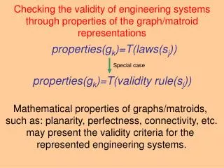
F F F F F F F Graph Representations - Definition Graph Representation Structure and Geometry Voltage, absolute velocity, pressure Relative velocity, deformation Force, Current, Moment Engineering system Current approach employs mathematical models based on graph theory to represent engineering systems
Input shaft Output shaft 1 4 C D A 2 5 3 6 B D C Overrunning Clutches Unidirectional Gear Train out= |in| Consider two engineering systems from the fields of mechanics and electronics.
1 4 C D A 2 5 3 6 B D C Building the graph representation of the system Graph Representation of the system maps its structure, the behavior and thus also its function
A 1 4 Input Source C D A C D 2 5 3 6 B D C B Output Electronic Diode Bridge Circuit Vout= |Vin| Consider two engineering systems from the fields of mechanics and electronics.
A 1 4 C D A C D 2 5 3 6 B D C B Building the graph representations of the systems Graph Representation of the system maps its structure, the behavior and thus also its function
A 1 4 C D A C D 2 5 3 6 B D C B Building the graph representations of the systems The two engineering systems possess identical graph representations
Solving Design Problem FR’={ out= | in| } Graph Representation FR={ out= |in| } FR’’={ Vout= | Vin| } Mechanics Electronics We shall now consider a hypothetical design problem for inventing the unidirectional gear train
A C D B Solving Design Problem FR’={ out= | in| } Graph Representation FR={ out= |in| } FR’’={ Vout= | Vin| } Mechanics Electronics In electronics there is a known device satisfying this functional requirement – diode bridge circuit
Detailed Transformation from Kinematic system into Static Augmenting the geometry to the graph. Constructing the dual graph. The meaning of a directed edge in the dual graph: e=<t,h> is the flow (force) acting upon the head vertex (joint) by the edge (rod). The force in rod 4** acts upon the ground in this orientation. Constructing its topology. Kinematic system. O O Constructing the corresponding graph B 3 3 2* 4* A (CCW) B The topology arrow and the force arrow are in the same direction -> compression.Inverse directions - tension The type is compression. A (CCW) 3* (CW) 2 4 2 4 I I Two choices? The direction of the force in rod 4**. The force in rod 3** acts upon the ground in this orientation. The external force acts upon joint I 4 (CW) The direction of the force in rod 3**. Vertex I corresponds to joint I. 2 (CW) (CW) O2 O4 O The type is tension. O2 O4 O3 1 Adding the geometry. 1 1 Edge 2 is the potential source that corresponds to the driving link 2. Link 2 is the driving link. Vertex O2 corresponds to joint O2. Edge 3 corresponds to link 3. Faces I and O are adjacent. Vertex A corresponds to joint A. The potential source, edge 2, is between the two adjacent faces I and O in the original graph. Therefore, in the dual graph it corresponds to the flow source and it is between the two adjacent vertices I and O. Edge 4 is common to the two adjacent faces I and O thus the dual edge 4* is between the two adjacent vertices I and O. The relative velocity of link 2 corresponds to the potential difference of edge 2. The relative velocities of links 3 and 4 correspond to the potential differences of edges 3 and 4. The relative linear velocity corresponds to the potential difference. Edge 3 is common to the two adjacent faces I and O thus the dual edge 3* is between the two adjacent vertices I and O. O4 For consistency, the direction of the edge in the dual graph is defined by rotating the edge in the original graph in CCW direction. Vertices B and O4 correspond to joints B and O4, respectively. We can contract the edges with potential difference equal to zero. The kinematic analysis yields the magnitudes and directions of the angular and relative linear velocities. Edges 4 and 1 correspond to link 4 and the fixed link 1, respectively. 3** Reference face O corresponds to reference vertex O. 4** The angular velocity in CW corresponds to compressing force. Potential differences in edges 3 and 4 correspond to flows in edges 3* and 4*. Potential differences in the original graph correspond to flows in the dual graph. Potential differences of edge 2 corresponds to the flow in edge 2*. The angular velocity is CCW which corresponds to a tension. Face I corresponds to vertex I. Building the corresponding truss. I 4** O4 (tension) (compression) 3** (compression) O3 The dual graph. The corresponding truss.
dual dual dual We obtain the dual systems. We have systematically developed a new variable in statics: Since linear velocity is associated with a joint in the linkage, its dual variable is associated with the face in the truss What is a counterpart to the absolute linear velocity of a joint in statics Joint Face + At first, what is this absolute velocity? + B O3 3 The relative linear velocity of the link 3 corresponds to the force in the rod 3**. The relative linear velocity of the input link corresponds to the external force. 1.The absolute linear velocity has a property of potential. The relative linear velocity of the link 4 corresponds to the force in the rod 4**. Velocity Force A Why? On the other hand we know that velocity corresponds to force. O4 4 Velocity of a joint Face Force Absolute linear velocity corresponds to face force. 2 3** Because, we can give any absolute linear velocity to the links, and they will satisfy the rule of compatibility (vector KVL). 4** O2 O4 I 1 1
The force in a rod is the result of subtraction of its two adjacent Face Forces P 2 A 4 1 B 3 O 5 R
One of the applications of FF - Characterization of the dead center position of the mechanism. O 2 7 1 4 4 5 3 O 2 5 3 7 O A C 1 6 6 2,3 5,7 C A 6 In this case, the faces B and O (i.e., the reference vertex) of the truss have the same face force which indicates that: (ii) links 5 and 7 are collinear. (i) links 2 and 3 are collinear, and These two conditions ensure that the mechanism is in a dead center position.
Characterization of all the dead Center Positions using Face-Force Given mechanism topology
12 12 2 2 4 8 4 3 3 7 5 9 1 7 1 9 5 6 6 10 10 11 11 8 Rigid ???? 2 ’ 12 ’ 4 ’ 8 ’ 3 ’ 2 ’ 1 ’ 7 ’ 5 ’ 9 ’ 12 ’ 8 ’ 6 ’ 4 ’ 10 ’ 3 ’ 9 ’ 7 ’ 1 ’ 1 1 ’ 5 ’ 6 ’ 10 ’ R’ 11 ’ R’ Definitely locked !!!!! Revealing Singular Positions Through the Duality relation Due to links 1 and 9 being located on the same line By means of the duality transformation, checking the stabiliy of trusses can be replaced by checking the mobility of the dual linkage.
USING THE DUALITY TRANSFORMATION FOR REVEALING SINGULARITY POSITIONS
Designing an active torque amplifier FR’1={ out= in } FR’2={ Fout= kFin } Graph Representation FR1={ out= in} FR2={ Tout= kTin; k>>1} FR’’1={ Vout= Vin } FR’’2={ Iout= kIin } Mechanics Electronics Solving a real design problem through by means of the approach
Designing an active torque amplifier Solving a real design problem by means of the approach
Designing an active torque amplifier FR’1={ out= in } FR’2={ Fout= kFin } Graph Representation FR1={ out= in} FR2={ Tout= kTin; k>>1} FR’’1={ Vout= Vin } FR’’2={ Iout= kIin } Mechanics Electronics Solving a real design problem through by means of the approach
Output shaft Screw thread Input shaft Engine Work principle of an active torque amplifier The four working modes of the active torque amplifier mechanism
Another Transformation Alternative Graph Representation
Design through mathematically related representations Graph Representation Graph Representation of another type Statics Kinematics Same approach can be applied to graph representation
Graph Representation Graph Representation of another type FR’’={ out>> in } FR’={ Fout>>Fin } FR’’’={ out>> in } FR={ Pout>>Fin } Statics Kinematics Designing a force amplifying beam system
G 0 G B A B A 1 2 3 4 5 B A B A C G C I II III IV C G C G G 0 2 4 3 5 C C B B wout 1 A A G G win Graph Representation Graph Representation of another type G FR’’={ out>> in } FR’={ Fout>>Fin } FR’’’={ out>> in } FR={ Pout>>Fin } Statics Kinematics Known gear train satisfying this requirement is the gear train employed in electrical drills.
A general perspective on the result introduced in this talk through the network of the graph representations.
C C C C DESIGN A BEAM FORCE AMPLIFIER ? !
Complete correspondence between these two domains of concepts DESIGN A UNIDIRECTIONAL PLANETARY SYSTEM THE SIZE OF DOMAIN OF CONCEPTS FOR UNIDIRECTIONAL TRAIN IS TWO THE SIZE OF DOMAIN OF CONCEPTS FOR RECTIFIER CIRCUIT IS TWO ! ! ?
DESIGN A TRUSS FORCE AMPLIFIER Shaper mechanism ? !
Thank you!!! This and additional material can be found at: http://www.eng.tau.ac.il/~shai