Download
1 / 1
10 likes | 174 Views
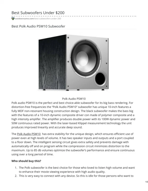
Experimental Results Distortion caused by the mechanical properties of the cone: Correction: Subwoofer input of 60 Hz. Subwoofer output of 60 Hz with no correction. Note distortion harmonics at 120 and 180 Hz. Subwoofer output of 60 Hz with the servo feedback correction.

E N D
Experimental Results • Distortion caused by the mechanical properties of the cone: • Correction: • Subwoofer input of 60 Hz. • Subwoofer output of 60 Hz • with no correction. • Note distortion harmonics • at 120 and 180 Hz. • Subwoofer output of 60 Hz with • the servo feedback correction. • The 120 Hz harmonic is attenuated • from -46.5 dB to -65db. Figure 3. Distortion produced by the subwoofer cone Figure 4a. Original Tone Figure 4b. Tone without correction Figure 4c. Tone correction Servo Feedback Control of an Audio Subwoofer Dalimar Vélez Vega Advisor: Shawn Hunt University of Puerto Rico Mayaguez Campus Overview An audio subwoofer reproduces the lowest frequencies we can hear, from about 20 to 200 Hz. The subwoofer cone motion is subject to harmonic distortion because of the large excursions needed to reproduce these frequencies. The goal of this project is to implement a servo feedback control system that will reduce the harmonic distortion. An accelerometer measures the movement of the cone. The feedback control adjusts to minimize the difference between the actual output measured with the accelerometer and the desired output. The analog solution to this problem is available commercially, but the digital version is not. This project successfully designed and built the servo-controlled subwoofer and integrated it with a small speaker that covers the rest of the audio spectrum. • LMS Adaptive Filters • LMS Adaptive Filters have the ability to adjust their parameters automatically and their design requires little or no prior knowledge of the signal or noise characteristics. The LMS filter is a FIR filter whose weights are changed with the following equation: • w(n+1)=w(n) + μx(n) e(n), • where w(n) is the weight vector at time n, x(n) is the input, and e(n) is the difference between the desired output and the actual output. Figure 1. Block Diagram of the servo-controlled subwoofer • Theoretical Background • Harmonic and Total Harmonic Distortion (THD) • A harmonic [1] is a signal or wave whose frequency is an integral multiple of the frequency of some reference signal. Let f represent the main, or fundamental, frequency of a sound wave. This frequency, usually expressed in hertz, is the frequency at which most of the energy is contained, or at which the signal is defined to occur. A harmonic is then • where n is the harmonic number, so the second harmonic has a frequency 2f. • Let w represent the wavelength of the signal in a specified medium. • where n is the harmonic number, so the second harmonic has a wavelength of w/2,. Signals occurring at frequencies of 2f, 4f, 6f, etc. are called even harmonics; the signals at frequencies of 3f, 5f, 7f, etc. are called odd harmonics. • Total harmonic Distortion (THD) is the amount of undesirable harmonics present in an output audio signal expressed as percentage • Sampling and Reconstruction • A traditional method of sampling and reconstruction of a signal is based on the Nyquist theorem. This says that the sampling frequency (fs) must be at least twice the bandwidth of the signal being sampled. • where fm is highest frequency of the signal being sampled. • Subwoofer • A subwoofer is a special speaker used to reproduce only the lower portion of the audible frequency spectrum usually from 200 Hz down to or below 20 Hz. True subwoofers should be able to play useful audible information down close to 20 Hz (the lower limit of human hearing). Most subwoofers feature one or more speaker drivers measuring ten or more inches in diameter. There are two primary types of subwoofer – powered and non-powered. • In a perfect world, a speaker driver would move in exact and perfect relation to the signal being applied to it, but in real life the driver’s mass, the air pressure on it, the driver’s speed and other factors make this impossible [3]. Figure 2. Subwoofer Assembly [2] and the Infinity Entra Sub Two Powered Subwoofer [3].