APS Formation Sensor
E N D
Presentation Transcript
APS Formation Sensor Optics Dennis Charles Evans 15 March 2002
Optical Studies • Optical Design • Centroid Error Modeling • Summary • Back-up Information
Optical Characteristics • Telecentric Design (Modified Aerial Mapping Camera) • Changes in length do not change plate scale • Aperture = 100 mm (selected) • Optical Speed = f/5 (selected for ease of fabrication) • Focal Length = 500 mm (result) • Optical Design Half Angle FOV = 5.0 degrees (larger angles possible) • Plate Scale Needed for Point Design • Based on deployed element distribution • 5 km at 50 km (source) = 50 mm at 500 mm (focal plane) • 4096×0.013 = 53.248 mm typical detector • Half angle = 2.9 degrees • The tracker could handle a wider distributed source by using a larger detector or series of detectors. • Glasses: Schott SK4, F 5, LF 5 • May have to replace with radiation hard glasses • Design is internally baffled only • An external sunshade may be needed for a particular instrument
Optical Characteristics • Tolerance Analysis (not done, not expected to be a problem) • Design was selected to be insensitive to changes in focus. • Thermal characteristics similar to CHyMERA. • Thermal changes in index of refraction change focus more than mechanical expansion of lens holder. • A matched lens holder coefficient of expansion will not make an thermally insensitive design. • CHyMERA required near zero CTE (GFRP) because of thermal gradients perpendicular to optical axis (banana effect) • Commercial Tilts & Decenters acceptable • Implications • Proportional Thermal Controller (±3 degree C range) • Would like Lenses near ambient and Detector near 0 C • for simplicity detector housing should be above freezing
Optical Characteristics • Ghost images will result from reflections at lens and filter surfaces • Filter ghosts will be centroid aligned with beacon image • Filter ghost will be 0.004 of image or lower • Lens ghosts will be generally diffuse • Reference to other designs implies lens ghosts will be 0.001 to 0.0001 of image or lower. • Flat Field Monitoring is provided by illuminating a diffuser plate on the back of the closed aperture door • Wavelength filters are needed for resolving multiple beacons on same daughter or daughters very close together. • depending on stability, beacons could be turned off and on for identification and angular separation
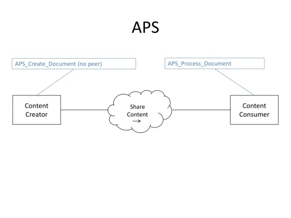
Telecentric Aerial Photo Lens SK4 = 3.57 g/cc F5 = 3.47 g/cc LF5 = 3.22 g/cc SK4 F5 SK4 SK4 LF5 SK4 100 mm diameter Telecentric Stop
Basic Mounting & Internal Baffle Layout Defining 100 mm diameter Telecentric Stop Pseudo Stop Aperture Detector
Centroid Error Modeling • Uniform Defocused Image Model • Photoelectron Random Normal Statistics
Centroiding Model Results • Electro-Optical system throughput was calculated for 0.001 sec cycle. • 3 x 3 and 9 x 9 pixel centroiding with 40 000 PE/px, integrated for 10 cycles (0.01 sec), results in noise statistics about 5 x better than the 0.012 arc-sec error needed. • For 1000 cycle averaging, the centroid error is 0.0005 arcsecond; equivalent to 0.150 mm at 50 km, much better than the basic requirement. • A significant noise margin exists for the point design! The margin on noise can be greatly improved if needed. • Noise is reduced most effectively by increasing the number of PE/px. • Well depth is being improved for APS arrays. CCD arrays have an order-of-magnitude deeper wells at present.
Wide Flux Design Range • Electro-Optical system throughput was evaluated at 0.001 second cycle rate, not 1 second. • System time constant is likely to be in the seconds to minutes range. • Position requirement of 3 mm at 50 km was 0.012 arcsecond • Integration of Centroid for 1000 cycles gives a position error of 0.0001 pixel width (1/22 of design goal) • Centroid error is 0.0005 arcsecond; equivalent to 0.150 mm at 50 km. • Implication: • System has more capability than required • Could be reduced in size by an order-of-magnitude in volume
Optical Performance Summary • Thermally stable Telecentric Optical Design • analytically attractive • flight proven design concept • Position error due to photoelectron statistical noise is well below the 0.012 arcseconds needed for this design • If 3mm error at 50km is all that is needed, the size of the sensor system might be reduced significantly, possibly by a factor of 10 in mass.
Lens Element Mass ELEMENT VOLUME DATA: Values are only accurate for plane and spherical surfaces. Element volumes are computed by assuming edges are squared up to the larger of the front and back radial aperture. Volume cc Density g/cc Mass g Element surf 2 to 3 372.375669 3.570000 1329.381137 Element surf 4 to 5 1111.283091 3.570000 3967.280633 Element surf 6 to 7 670.546997 3.470000 2326.798080 Element surf 11 to 12 786.881150 3.220000 2533.757302 Element surf 13 to 14 832.146110 3.570000 2970.761614 Element surf 15 to 16 249.365462 3.570000 890.234699 Total Mass: 14018.213466
Photo Electron Noise Modeling • Photo Electron Noise is related to the square root of the signal. • The square root of the signal is approximately 1 sigma deviation. • The noise is modeled as a Normal (Gaussian) distribution with a one sigma standard deviation equal to the square root of the signal. • Procedure for generating normal distribution noise • Computer language generates pseudo random number from 1 to 1000 and scales to 0.001 to 1.000 • Function converts number to random normal distribution.
-5 0 +5 68.3% 95.5% 99.7% Normal Distribution
1 Selection of random value on vertical axis produces random normal distribution on horizontal axis 0 -5 0 +5 Random Normal Signal Distribution
Centroiding Model 9 TrackerFocalPlane 40000 Centroid is at 12,8 = 39572 Array[J;I] A[;1] A[;2] …… 0 0 0 0 0 0 0 0 0 0 0 0 0 0 0 0 0 0 0 0 0 0 0 0 0 0 0 0 0 0 0 0 0 0 0 0 0 0 0 0 0 0 0 0 0 0 0 0 0 0 0 0 0 0 0 0 0 0 0 0 0 0 0 0 0 0 0 0 0 0 0 0 0 0 0 0 0 0 0 0 0 0 0 0 0 0 0 0 0 0 0 0 0 0 0 0 0 0 0 0 0 0 0 0 0 0 0 0 0 0 0 0 0 0 0 0 0 0 0 0 0 0 0 0 0 0 0 0 0 0 0 0 0 0 0 0 0 0 0 0 0 0 0 40128 39672 39884 39948 39964 39804 39752 40060 40300 0 0 0 0 0 0 0 0 0 0 0 40128 39844 40032 39504 39880 40380 40004 40156 39992 0 0 0 0 0 0 0 0 0 0 0 40236 39604 39792 39800 40052 39876 40116 39948 40264 0 0 0 0 0 0 0 0 0 0 0 39820 40208 40092 40572 40092 39816 40028 40124 39808 0 0 0 0 0 0 0 0 0 0 0 39976 39960 39892 39944 39572 39844 40252 40024 40140 0 0 0 0 0 0 0 0 0 0 0 39936 40280 40100 39872 40124 40220 39836 39740 39696 0 0 0 0 0 0 0 0 0 0 0 39940 40420 39924 39832 39980 39524 39944 40144 39880 0 0 0 0 0 0 0 0 0 0 0 39936 40168 39976 40228 40040 40104 39840 40068 39704 0 0 0 0 0 0 0 0 0 0 0 40028 39776 40008 40128 39904 40080 39840 40112 40124 0 0 0 0 0 0 0 0 0 0 0 0 0 0 0 0 0 0 0 0 0 0 0 0 0 0 0 0 0 0 0 0 0 0 0 0 0 0 0 0 0 0 0 0 0 0 0 0 0 0 0 0 0 0 0 0 0 0 0 0 0 0 0 0 0 0 0 0 0 0 0 0 0 0 0 0 0 0 0 0 0 0 0 0 0 0 0 0 A[1;] A[2;] etc.
Floor at 1E-6 Near ghost between 1/1000 and 1/10,000. “Diffuse” lens ghosts. Typical Reflection Ghosts
Floor at 1E-4 Near ghost is about 1/600. General ghosts between 1/600 to 1/1000. All look like surface ghosts. Typical Lens & Filter Reflection Ghosts