Download
1 / 67
720 likes | 930 Views
Learn about GSM standards and multiple access methods - FDMA, TDMA, and CDMA. Understand the channel structures, frame counts, time slots, and duplex channels in GSM networks. Explore authentication, handover procedures, security services, and key generation in GSM technology.

E N D
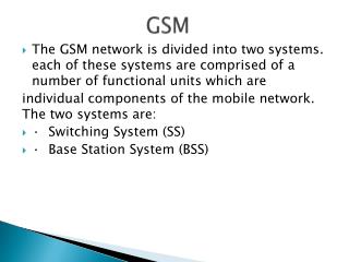
Frequency Division Multiple Access (FDMA) Frequency 1 ch Frequency 2 ch Frequency N ch Time Division Multiple Access (TDMA) Time Time Time Slot 1 Slot 2 Slot N ch ch ch Code Division Multiple Access (CDMA) Code Sequence 1 ch Code Sequence 2 ch Code Sequence N ch Multiple Access Methods
Power All Channels Share Same RF Band Freq Code 4 Ch 1 Ch 2 Ch 3 Ch 4 MAC Alternatives - CDMA Code 1 Code 2 Code 3
Time Domain Uplink Slot 0 Slot 1 Slot 7 Frequency 1 ch ch ch ch Frequency 2 ch ch ch ch ARFCN 1 Frequency 124 ch ch ch ch Frequency Domain Downlink Slot 0 Slot 1 Slot 7 Frequency 1 ch ch ch ch Frequency 2 ch ch ch ch Frequency 124 ch ch ch ch 992 Duplex Physical Channels Available Physical Channel Structure Used in P-GSM900
Frame (Count) Frame (Count + 1) 0 1 2 3 4 5 6 7 0 1 2 3 4 5 6 7 TDMA Operation in GSM Full Rate DOWNLINK Frame (Count) Frame (Count + 1) 0 1 2 3 4 5 6 7 0 1 2 3 4 5 6 7 UPLINK BS MS1 MS7 MS0 MS5
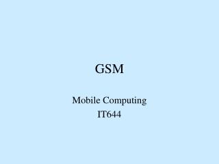
higher GSM frame structures 5 7 8 1 2 4 6 3 4.615 ms 546.5 µs 577 µs GSM - TDMA/FDMA 935-960 MHz 124 channels (200 kHz) downlink frequency 890-915 MHz 124 channels (200 kHz) uplink time GSM TDMA frame GSM time-slot (normal burst) guard space guard space S user data tail tail user data S Training 1 3 1 57 bits 3 bits 57 bits 26 bits
MS Transmission Band : 890 – 915 MHZ BS Transmission Band : 935 – 960 MHZ 45 MHz
Channels for Two-Way Communications Frequency Division Duplex Frequency separation between uplink and downlink channel pairs 1 2 3 1 2 3 frequency Uplink RF carrier channels Downlink RF carrier channels Downlink Uplink
GSM Handover To Frequency 9 Time Slot 7 MSC From Frequency 6 Time Slot 3 BSS MS Subscriber Set BSS • Lanline switched at MSC • Frequency and time slot changed at MS
1: calling a GSM subscriber 2: forwarding call to GMSC 3: signal call setup to HLR 4, 5: request MSRN from VLR 6: forward responsible MSC to GMSC 7: forward call to current MSC 8, 9: get current status of MS 10, 11: paging of MS 12, 13: MS answers 14, 15: security checks 16, 17: set up connection PSTN Mobile Terminated Call 4 HLR VLR 5 8 9 3 6 14 15 7 calling station GMSC MSC 1 2 10 13 10 10 16 BSS BSS BSS 11 11 11 11 12 17 MS
1, 2: connection request 3, 4: security check 5-8: check resources (free circuit) 9-10: set up call PSTN Mobile Originated Call VLR 3 4 6 5 GMSC MSC 7 8 2 9 1 MS BSS 10
MS MTC BTS MS MOC BTS paging request channel request channel request immediate assignment immediate assignment paging response service request authentication request authentication request authentication response authentication response ciphering command ciphering command ciphering complete ciphering complete setup setup call confirmed call confirmed assignment command assignment command assignment complete assignment complete alerting alerting connect connect connect acknowledge connect acknowledge data/speech exchange data/speech exchange MTC/MOC
4 types of handover 1 2 3 4 MS MS MS MS BTS BTS BTS BTS BSC BSC BSC MSC MSC
Handover decision receive level BTSold receive level BTSold HO_MARGIN MS MS BTSold BTSnew
Handover procedure MSC MS BTSold BSCold BSCnew BTSnew measurement report measurement result HO decision HO required HO request resource allocation ch. activation ch. activation ack HO request ack HO command HO command HO command HO access Link establishment HO complete HO complete clear command clear command clear complete clear complete
Security in GSM • Security services • access control/authenticationuser SIM (Subscriber Identity Module): secret PIN (personal identification number • confidentiality • voice and signaling encrypted on the wireless link (after successful authentication) • anonymity temporary identity TMSI (Temporary Mobile Subscriber Identity) • newly assigned at each new location update (LUP) • encrypted transmission • 3 algorithms specified in GSM • A3 for authentication (“secret”, open interface) • A5 for encryption (standardized) • A8 for key generation (“secret”, open interface) • “secret”: • A3 and A8 available via the Internet • network providers can use stronger mechanisms
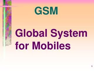
GSM - authentication SIM mobile network RAND Ki RAND RAND Ki 128 bit 128 bit 128 bit 128 bit AC A3 A3 SIM SRES* 32 bit SRES 32 bit SRES SRES* =? SRES MSC SRES 32 bit Ki: individual subscriber authentication key SRES: signed response
GSM - key generation and encryption MS with SIM mobile network (BTS) RAND Ki RAND RAND Ki AC SIM 128 bit 128 bit 128 bit 128 bit A8 A8 cipher key Kc 64 bit Kc 64 bit SRES data encrypteddata data BSS MS A5 A5
Location Areas and Cell Areas Cell Global Identification Number MCC MNC LAC CI Location Area Identification (LAI) Acronyms MCC - Mobile Country Code (Same as in the IMSI) –3 digits. MNC - Mobile Network Code (same as in the IMSI – 2 digits. LAC - Location Area Code used to identify a location area within a GSM PLMN – 2 octets. LAI - Location Area Identification CI - Cell Identity – 2 octets.
Registration Sequence Source: An Introduction to GSM Redl, Weber and Oliphant
Location Area BSS BSS Mobile Switching Centre DN - Location Area - Mobile ID DN Mobile Station PSTN BSS BSS BSS Location Area Paging a Mobile Station
Mobile Station Identification Numbers Used in GSM • International Mobile Equipment Identity (IMEI) • Uniquely identifies mobile station equipment • Burnt in by the equipment manufacturer • TAC – Type Approval Code (6 digits) • FAC – Final Assembly Code (2 digits) • SNR – Serial Number (6 digits) • SP – Spare (1 digit) • International Mobile Subscriber Identity (IMSI) • IMSI is assigned to a MS at subscription time • IMSI uniquely identifies a given MS • IMSI is transmitted over the radio path only when necessary • MCC – Mobile Country Code [3 digits] (home country) • MNC – Mobile Network Code [2 digits] (home GSM PLMN) • MSIN – Mobile Subscriber Identification Number (10 digits) • NMSI – National Mobile Subscriber Identity • Temporary Mobile Subscriber Identity (TMSI) or (TIMSI) • TMSI is assigned to a MS by the VLR • TMSI uniquely identifies a MS within the area controlled by a given VLR IMEI (15 digits) SP TAC FAC SNR IMSI (15 digits) MCC MNC MSIN NMSI TMSI (32 bits max)
GSM Test SIM 2To 92316 005 Subscriber Identity Module (SIM) • Contains: • International Mobile Subscriber Identity (IMSI) • Authentication key (Ki) • Personal Identification Number (PIN) • Subscriber information • Access control class • Cipher key (Kc)* • Temporary Mobile Station Identification (TMSI)* • Additional GSM services* • Location Area Identity (LAI)* • Forbidden Public Land Mobile Numbers (PLMNs)* • *Updateable by network
GSM Test SIM 2To 92316 005 Subscriber Identity Module (SIM)Hardware Spec Highly Secure Processor Contact Type - Smart Card Communication via serial IO Data Rate 1MHz Contains ROM, RAM and EPROM
SIM Security Functions • Pin Code to unlock the mobile station. • 3 wrong attempts at PIN and SIM is blocked. • SIM may be unblocked with PIN Unblock Code (PUK). • 10 attempts at PUK and SIM is permanently disabled. • Second PIN and second PUK available in Phase 2 to support Closed User Groups and Fixed Dial Numbers. • SIM and Phase 2+ • SIM Application Toolkit allows user applications (e.g. electronic banking) to be run on the SIM
Routing Calls Automatically To Mobile Stations
Trunks MSC Trunks Local Exchange PSTN MSC Directory Number Spectrum in MSC MSISDN Used to reference home subscribers MSRN Used to reference visiting subscribers MSC Directory Number Allocation
Land to Mobile Call Routing Mobile Located in Non-Home MSC Area HLR MSISDN MSRN 3 4 BSS 1 Home MSC MSISDN MSISDN 2 1 BSS 2 TMSI TMSI MSRN PSTN 5 9 10 Visited MSC BSS 1 MSRN 6 BSS 2 7 8 MSRN TMSI & LAC Signalling VLR Voice Path
HLR MSISDN MSRN BSS 1 MSISDN Home MSC PSTN BSS 2 MSRN TMSI & LAC VLR Land to Mobile Call Routing Mobile in Home MSC Area MSISDN TMSI TMSI
BSS 1 Home MSC BSS 2 MSISDN MSISDN HLR PSTN MSRN TMSI MSISDN BSS 3 TMSI Visited MSC BSS 4 MSRN TMSI & LAC VLR Land to Mobile Call Routing Intelligent PSTN Routing
BSS 1 Home MSC BSS 2 MSISDN MSISDN HLR Gateway MSC PSTN MSRN TMSI BSS 1 MSISDN TMSI Visited MSC MSRN BSS 2 MSRN TMSI & LAC Signalling Voice Path VLR Land to Mobile Call Routing Routing Via a Gateway MSC
Landline network Home GSM system Visited GSM system Home MSC PSTN HLR VLR Mobile Registers Update Location. No MSRN, use LMSI Subscriber Data Incoming Call Need MSRN For LMSI Get Route MSRN MSRN Incoming Call Get Route Need MSRN For LMSI MSRN MSRN Dynamic Allocation of MSRN
Phases of a Location Update • 1) Request for Service • 2) Authentication* • 3) Update Location Registers • 4) Ciphering* • 5) TMSI Reallocation • *Phase might not occur
Um A B New VLR MSC BSS MS Channel Request (on RACH) Dedicated Signalling Channel Assignment (on AGCH) Location Update Request TMSI, LAI (on SDCCH) Location Update Request 7 1 2 3 9 4 8 5 6 Location Update Request Request IMSI Request IMSI IMSI Acknowledge IMSI Acknowledge Mobile Location Update:Request for Service
MSC MS 10 11 12 13 14 15 16 17 Mobile Location Update : Authentication B D New VLR HLR AUC Get Authentication Parameters IMSI Get Authentication Parameters IMSI Authentication Parameters RAND, SRES, Kc Authentication Parameters RAND, SRES, Kc Authenticate Mobile Station RAND Authenticate Mobile Station RAND Authenticate Response SRES Authenticate Response SRES
D D New VLR Old VLR HLR Update Location MSRN Location Updated Customer Profile 18 19 20 21 De-register Mobile Station Mobile Station De-registered Mobile Location Update: Update Location
Um A B New VLR MSC BSS MS Set Ciphering Kc Encipher Command Kc Cipher Mode Command 22 24 23 25 26 Cipher Mode Complete Encipher Complete Mobile Location Update:Ciphering
Um A B MSC BSS MS New VLR Location Update Accept new TMSI Location Update Accept new TMSI 29 27 32 28 30 31 Location Update Complete Clear Signalling Connection Release Radio Signalling Channel Clear Complete Mobile Location Update:TMSI Reallocation
Mobile-to-Land Call Scenario
Public Land Mobile Network Fixed Public Land Network Voice Trunk to PSTN PSTN Line MSC MSC Voice Trunk Radio Channel BSC Voice Trunk BTS BSC Mobile Station Required Facilities for a Mobile-to-Land Call 1. Radio channel between Mobile Station and BTS selected by the BSC 2. BSC – BTS voice trunk selected by the BSC 3. MSC – BSC voice trunk selected by the MSC 4. MSC – PSTN voice trunk selected by the MSC 5. Line from PSTN end switching office to Fixed Station (permanent link) BSC - Base Station Controller BTS - Base Transceiver Station MSC - Mobile Switching Centre PSTN - Public Switched Telephone Network
Phases of a Mobile-to-Land Call • Request for Service • Authentication* • Ciphering* • Equipment Validation* • Call Set-up • Handover(s)* • Release • * Phase might not occur • Note: Detail for authentication and ciphering is not shown. It is the same as in the location registration update scenario.
Um A B New VLR MSC BSS MS Channel Request Dedicated Signalling Channel Assignment 1 2 3 4 5 Service Request TMSI, LAI Service Request TMSI, LAI Service Request TMSI, LAI Mobile-to-Land Call Request for Service
MSC 6 7 8 9 Mobile-to-Land Call Equipment Validation MS EIR IMEI Request IMEI Response Check IMEI (IMEI) IMEI Check Results
Um A B VLR MSC BSS MS Call Setup Request Access Subscriber Data Subscriber Data 10 12 16 15 13 17 11 14 Call Proceeding Assign Trunk & Radio Trunk No. Assign Radio Channel TCH Radio Assignment Complete (on TCH) Trunk & Radio Assignment Complete TCH Mobile-to-Land Call Set-up
MS PSTN MSC Network Set-up (Dialled DN, Trunk No.) Network Alerting 23 22 21 19 18 20 Alerting Connect (answer) Connect Connect Acknowledgement Mobile-to-Land Call Set-upContinued Note: Network Set-up, Network Alerting and Connect are generic terms. For SS7, the network set-up message would be Initial Assignment Message (IAM).
Um A PSTN MSC BSS MS Disconnect Network Release Release 1 3 4 6 2 5 7 Release Complete Clear Command Channel Release Clear Complete Mobile-to-Land CallMobile Initiated Release