Development of Ultra DMA Module for Hard Disk Controller Review
230 likes | 321 Views
This review discusses the development of an Ultra DMA module for a hard disk controller, including specifications, Verilog HDL RTL description, and behavioral modeling. It covers DMA functionality, PIO modes, timing simulations, constraints, and phases of Ultra DMA data transfer. The review also outlines individual tasks of team members and project goals.

Development of Ultra DMA Module for Hard Disk Controller Review
E N D
Presentation Transcript
IDE ControllerFeasibility Review Group Members Brian Kulig Graig Plumb James Pierpont Saif Shaikh Advisor Arun Ramanathan
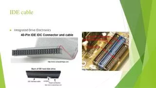
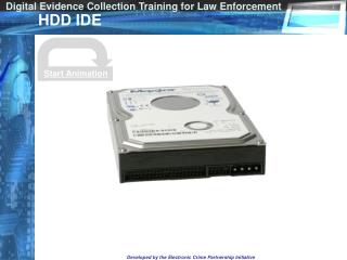
Development of an Ultra DMA Module for a Hard Disk Controller • Specifications – IDE ATA5 Standards • RTL Description of PIO and Ultra DMA (Direct Memory Access) Module in Verilog HDL (Support for PIO Modes 0 to 4 & UltraDMA Modes 0 to 4) • Behavioral description of the Hard Disk Interface • Functional and Timing Simulations using Cadence VerilogXL
Architecture IDE CHANNEL0 IDE FSM PIO MODULE To Hard Disk Fifo’s and Rest of System DMA MODULE PIO MODULE IDE FSM To Hard Disk Fifo’s and Rest of System DMA MODULE IDE CHANNEL1
PIO Design • 5 Modes 0 - 4, used for control signals • Timer, begins on start pulse • Signals dependent on rw • Timer reset at specific time • Example mode 0 resets at 67 • IORDY can delay system up to 1250 ns • Databus enabled by data write
Test Bench • It simulates controller for our module • It produces are varying waveforms for the different modes • Evolve into a hard disk with the implementation of UDMA
Phases of Ultra DMA Data Transfer • Initiating UDMA Data-In (Out) Burst • Data-In (Out) Transfer • Pausing Data-In (Out) Burst • Terminating Data-In (Out) Burst
Description of the Host • The Host Has: • A Read Buffer and a Write Buffer • Ability to cycle through and request all modes of data transfer • Ability to Calculate CRC Values as well as periodically send an error to the controller
CRC Error Checking Design • Process: • Both Devices are initialized with 4ABA • Value is modified on every STROBE pulse • using G(X) = X16 + X12 + X5 + 1 • Host ---> CRC ---> Controller • Bits 2 & 7 in Error Register go high • <----- 04 HARDWARE ERROR • Host Should Retry last command
Who’s doing What. • Saif: Program DMA mode RTL Code, Update Website • James: Program DMA mode RTL • Brian: Implement Error Checking, Describe Host in Behavioral Verilog • Graig: Interface PIO Mode with DMA, Describe Hardrive in Behavioral Verilog
Finishing Everything on Time • Our Goal is finishing on May 8th • We have all the tools and know how to use them. • We have all the specifications in hand. • All team members know their tasks
References • General IDE Information: • pcguide.com • hardwarecentral.com • ATA5 Specification: t13.org • Our Website: • www-unix.ecs.umass.edu/~sashaikh/ece559/index.html