Download
1 / 18
180 likes | 233 Views
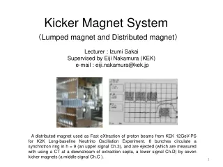
This study conducted over two weeks focused on testing and confirming the performance of a multi-unit strip-line kicker for the ILC, ensuring the rise time meets requirements. Beam extraction tests were carried out using a pulsed magnet kicker and local bump orbit to address kick angle issues. The setup included precise trigger control, digital delays, and stable beam storage improvements. Timing adjustments were crucial for achieving stable kicker pulse timing. Results showed stable beam extraction with minimal beam loss and jitter ratios within acceptable limits. Additional work is needed to address stored current reduction and dispenser corrections for the ATF2 beam line.

E N D
Fast kicker study Machine Time 2011/10/18~10/29(2 weeks) TB meeting 2011/01/14 T.Naito
ILC kicker Multi-units of strip-line kicker ILC kicker parameters
Single unit test(30cm long strip-line) (To confirm 3ns of the rise time of the strip-line kicker) • Time response measurement using 30cm long strip-line electrode. • The drive pulser(FID Co. Ltd) have 1.5ns rise time, 5kV peak voltage, 3MHz and 3000 burst pulse. • The measured rise time was 3ns, which meets the ILC requirement. Waveform of FID pulsr 5kv peak, 1.5ns rise time
Beam extraction test(1) • The beam extraction test was carried out to confirm the performance of the strip-line kicker. • The pulsed magnet kicker was replaced to two units of 60cm long strip-line kicker. • To help the lack of the kick angle, a local bump orbit and an auxiliary septum is used. Extraction kicker ATF2 Extraction line Damping Ring Kicker pulse (10kV) Kicker field
Beam extraction test(2) The time sequence is that , 10 bunches with 5.6ns bunch spacing beam is injected to the DR three times, 30 bunches total. The local bump orbit is excited gradually after all of beam is damped. The beam is kicked out bunch-by-bunch by the strip-line kicker. The local bump orbit is return to zero.
Kicker and PS location 6m cables Steer Mag(5mrad) The drive pulsers are located to the outside of the shielding. Strip-line kicker 60cm 9mm gap, 11mm gap
Pictures of the installed components Strip-line electrodes Aux. Septum FDI pulsers Bump PS and Septum PS
Programmable Digital delay Precise triggers for each pulser and the timing control is required. The pulse measurement by the scope and the timing control by digital delays consist the trigger timing feedback. The step of the digital delay is 60ps. The trigger system could keep the pulse timing in the range of 200ps.
Improvements for multi-bunch extraction Stable beam storage to the DR Previous experiment could not realize stable beam extraction, which come from unstable beam storage to the DR | Stable 5.6ns laser system for RF gun and other effort could cure the beam blow up at the inection. Timing adjustment circuit is newly installed We already understood FID pulser has timing shift at the burst mode, when changing the interval. | Timing adjustment circuit is used to make stable stable kicker pulse timing.
Multi-bunch extraction (30 bunches) with 308ns bunch spacing 2010/06/17 The intensity of each bunch is not flat and unstable. The horizontal beam position was distributed to two position.
Pulse train delay adjustment circuit w/o delay with delay Use for beam extraction
Multi-bunch Beam in the DR and the extraction line 30 bunches of the beam are stored to the DR, stably. Stable beam extraction was confirmed at the extraction line. The beam reach to the beam dump without any beam loss.
Orbit and jitter measurement Left figure shows the kick angle as a function of the pulse number. The kick angle of the multi-bunch distributes around 1%. It shows the difference of the kick field for each pulse. Right figure shows the kick angle jitter ratio for the kick angle as a function of the pulse number. The jitter ratio for the kick angle was distributed from 1x10⁻³ to 4x10⁻³ for each pulse. This value is larger than the single bunch jitter. The timing adjustment was not enough at this time.
Single bunch jitter Jitter 2.24e-6/3e-3=7.4e-4 Jitter 1.05e-6/3e-3=3.5e-4
Use for ATF2 beam We could confirmed the dispersion correction of the ATF2 beam line by the beam profile change of the MS1IP wire scanner. The measured size was limited to 1.4um due to the wire size.
Profile of the kick field and the jitter Plot shows the beam position at MQM16FF BPM, when scanned the kicker pulse timing. There is no flattop of the kick field and the jitter increased at the both side of the peak. To make stable beam kick, careful timing adjustment of four pulses is needed. 200ps
Problem 2hour Blue line: current Red line: v size 9 bunch 1 train Itot=2x10¹⁰ 9 bunch 3 train Itot=6x10¹⁰ single bunch 1 train The stored current decreased gradually when the multi-bunch operation. The current decrease depends on the stored current. Several minutes after the beam stop, the situation recovered. We suspect the heating of the strip-line electrode made such a happeninig.
Summary and Next step Fast kicker performance was confirmed by the multi-bunch beam extraction from the ATF-DR to the ATF2 extraction line. The kick angle stability 3.5x 10⁻⁴ was measured for the single bunch beam. The multi-bunch kick angle and the stability were measured. For the next step, we have to clear following problems, High current beam storage is limited by the horizontal aperture of the strip-line(9mm). The stored current reduction have to cure.