Download
1 / 22
220 likes | 237 Views
Explore the latest in wing tank flammability testing and modeling from the 2007 FAA International Aircraft Systems Fire Protection Working Group. Discover insights from current testing methodologies and ongoing/future research pursuits to enhance aircraft safety measures. Enhance your understanding of key parameters influencing wing tank flammability, with a focus on the interaction of various variables. Stay informed on the FAA's regulatory proposals and technological advancements in inerting system technologies to control flammability effectively.

E N D
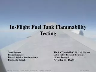
Federal Aviation Administration Wing Tank Flammability Testing and Modeling International Aircraft Systems Fire Protection Working GroupLondon, UK April 16-17, 2007 Steve Summer William Cavage Federal Aviation AdministrationFire Safety Branch
Outline • Overview • Current Testing • Scale Fuel Tank in Altitude Chamber • 727 Wing Tank in Wind Tunnel • Ongoing/Future Testing • Scale Al./Composite Fuel Tank in Wind Tunnel • A6 Composite Wing
Overview • Recent FAA rulemaking and regulation has focused on improving the safety of the fleet through more thorough systems analysis and ignition source reduction • FAA proposes to make a rule requiring flammability control of some or all CWTs with an emphasis on inerting system technologies • The flammability models (FAR Calculator, FTFAM, Rutgers Model) used by the FAA were all developed with CWTs in mind • Models use bulk fuel temperature to determine flammability which may not be as good an indicator of flammability for wings • Different secondary parameters (day temperature, fuel height, sun intensity, etc.) effect each tank differently • Flight test data caused us to look at our assumptions about wing tank flammability and more advanced model did not replicate data well
Wing Tank Flammability Parameters Flammability Drivers on Ground • Top skin and ullage are heated from sun • Hot ullage heats top layer of fuel, causing evaporation of liquid fuel • Bulk fuel temperature however, remains relatively low Flammability Drivers In Flight • Decreasing pressure causes further evaporation of fuel • Cold air flowing over the tank causes rapid cooling and condensation of fuel vapor • With a better understanding of these parameters and their interaction, we could develop, or modify existing models to aid in predicting fleet wide wing tank flammability
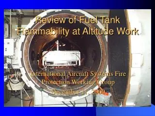
Current Testing - Scale Tank in Altitude Chamber • Used existing 17 ft3 aluminum fuel tank in altitude chamber • Has extensive array of thermocouples that were repositioned for this testing as well as gas sample ports for THC analysis • Used different fuel volumes, top heats, amb. temperatures, and F.P. to examine how these variables effect flammability under a fixed test cycle
Current Testing - Scale Tank in Altitude Chamber • Testing shows large increases in flammability with simulated wing heating only with below average fuel F.P. (115ºF) and unrealistic top temperatures • Need to repeat lower F.P. tests for certainty • Altitude effects the flammability in environmental chamber similar to observed in flight test CWT, not wing tanks • Tests have illustrated flammability from top heating probably less than bottom heating given similar F.P and fuel temperatures, but offers more flammability than isothermal heating • Fuel height does not seem to affect flammability because ullage is being heated conductively
Current Testing – 727 Wing Tank in Wind Tunnel • Outboard section of 727 wing containing the surge tank mounted in the low-speed section (max air speed of approximately 150 mph) of the FAA’s wind tunnel facility • Instrumented with 12 thermocouples and 1 hydrocarbon sample location • Radiant heaters used to heat top of wing to simulate ground conditions • Air passing over tank simulated flight conditions • Testing also conducted with heat applied to the bottom of the tank for comparative purposes
Current Testing – 727 Wing Tank in Wind Tunnel • Testing illustrated that even low speed aerodynamics at ambient pressures will cause a rapid decrease in flammability • From the flight test data available, it appears that this cooling effect greatly overpowers any effect due to depressurization. • Similar decreases in flammability were seen in bottom heated tests • Fuel temperature in bottom heated tests decreased much more rapidly than in top heated tests • Little change in results seen when wing was pitched at 15°
Ongoing/Future Testing – Scale Al./Composite Tank Wind Tunnel Tests • In process of modifying 9ft3 tank used in LOC ignition testing for mounting within the high-speed section of the wind tunnel • With this tank, we have the ability to easily change between an aluminum skin and composite skin to examine differences in flammability • Once mounted in wind tunnel, we will perform a series of tests similar to the 727 tests, but now with the ability to utilize much higher air speeds • The affect of variation in temperatures, air speed, fuel load, and skin type will be examined
Ongoing/Future Testing – A6 Composite Wing • A6 composite wing obtained from China Lake arrived at Tech. Center late March • Part of wing planned to be used in the low speed section of the wind tunnel for comparative tests to the 727 wing studies. • Other sections of the wing may be utilized for other testing (alt. chamber, HS wind tunnel section, etc)
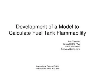
Wing Tank Flammability Modeling Studies • The Fuel Air Ratio Calculator is a tool developed by Ivor Thomas that uses basic inputs (fuel temperature, pressure, fuel type, fuel load) to compute the fuel air ratio for an isothermal ‘box’ • Looking at the FAA/NASA flight test data, this approach gives reasonable results for a wing tank while on the ground • In flight however, where condensation plays such a large roll, we see that this approach does not match existing data
Wing Tank Flammability Modeling Studies • Using ullage temperature instead of fuel temperature results in somewhat better results after take off
Wing Tank Flammability Modeling Studies • If we assume the following: • On the ground, fuel temperature drives evaporation of the liquid fuel and there are no condensation effects • Fuel temperature changes slowly in flight due to its large mass, but ullage temperature changes quickly and this rapid change in temperature, along with ambient pressure, is what drives flammability while in flight • The algorithm used for input into the FAR is: • On the ground ambient pressure and actual fuel temperature is used as inputs • In flight, the fuel temperature is modified by the change in ullage temperature at each time step
Wing Tank Flammability Modeling Studies • From limited data we have, it seems that this approach has some merit—though predicted numbers have a large absolute error, the tendency of fuel vapor concentration to follow the change in ullage temperature is clear • This perhaps is an indication of the interface between the fuel and ullage temperatures driving flammability, not the bulk fuel temperature • Modification of this temperature algorithm could result in further improvement of our ability to predict wing tank flammability • Datasets developed from all of our ongoing wing tank testing will be examined to help validate/improve this approach