Download
1 / 1
20 likes | 187 Views
1. 2. 3. 4. 5. 7. 7. 7. 7. 6. 6. 6. 6. 5. 5. 5. 5. 5. nA. 4. 4. 4. 4. 4. 3. 3. 3. 3. 3. nM. 2. 2. 2. 2. 2. 1. 800. 800. 1. 1. 1. 1. 0. 0. 0. 0. 0. 0. 1. 2. 3. 4. 5. 700. 700. 500. 8. 500. 500. 8. 600. 600. 400. 6. 6. 400. 400. 10.

E N D
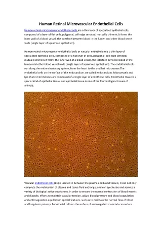
1 2 3 4 5 7 7 7 7 6 6 6 6 5 5 5 5 5 nA 4 4 4 4 4 3 3 3 3 3 nM 2 2 2 2 2 1 800 800 1 1 1 1 0 0 0 0 0 0 1 2 3 4 5 700 700 500 8 500 500 8 600 600 400 6 6 400 400 10 nA 8 4 4 200 200 200 nA 6 4 2 100 2 100 100 2 0 0 0 0 0 0 6 0 0 1 1 2 2 3 3 4 4 5 5 6 7 0 0 1 1 2 2 3 3 4 4 5 5 6 6 7 7 7 5 4 3 2 1 0 0 1 2 3 4 5 The studies of single human retinal lipofuscin granules using atomicforce and near-field optical scanning microscopy. Astafiev A.A.1 *, Petrukhin A.N.1 **, Sarkisov O.M.1 Dontsov A.E. 2, Feldman T.B.2 , Ostrovsky M.A.2# 1. Institute of Chemical Physics, Moscow, Kosygin st., 4, 117977 2. Institute of Biochemical Physics, Moscow, Kosygin st., 4, 117977 E-mail:*astafiev@8ka.mipt.ru **petrukhin@chph.ras.ru #ostrrovsky@gagarinclub.ru Introduction: Lipofuscin (LF) is a conglomerate of lipids, proteins, organic molecules and metals which accumulates in tissues with high oxidative stress. Particularly it is present in Retinal Pigment Epithelium (RPE) cells in form of yellow-brownish granules of micron size [1]. LF accumulation has a 99% correlation with a age-related macular degeneration – eye disease which causes vision distortion or even blindness among elderly people. This disease is thought to resulted from reactive oxygen intermediates (including hydrogen peroxide, singlet oxygen and superoxide anion radical) generation in LF upon the blue-light excitation [2]. LF contain a variety of blue-absorbing orange-emitting fluorofores among them two: piridinium bis-retinoid A2E and its isomer iso-A2E have been identified as being the major contributors to the orange fluorescence. It was shown that A2E has an ability to generate reactive oxygen species when exposed to blue light [4], yet it isn’t clear whether its contribution in phototoxicity of lipofuscin is dominant.The investigation of single granule’s shape morphology and fluorophores distribution was aimed to clear up the role of the fluorescent compounds in LF phototoxic properties. Due to the small size of the granules this measurements were only attainable using atomic force and near-field scanning probe microscopes Retinal Pigment Epithelium (RPE) Rod Outer Segments Electron micrograph of human RPE. Lipofuscin granules are marked with sick arrows. LF fluorescence spectrum at different excitation wavelength. Structures of A2E and iso-A2E The atomic force microscope (AFM) probes the surface of a sample with a sharp tip, a 10-20 mm long with typical tip curvature radius of 10 nm. The tip is located at the free end of a cantilever that is 100 mm long. The system vibrates a stiff cantilever near its resonant frequency (typically 250 kHz) with amplitude of a few tens to hundreds of angstroms. Then, it detects changes in the resonant frequency or vibration amplitude as the tip comes near the sample surface. The spacing between the tip and the sample is kept about 0.1-10 nm. By keeping the resonant frequency or amplitude constant, the system also keeps the average tip-to-sample distance constant. The motion of the scanner is used to generate the data set (topography image). In every scan of the sample with AFM phase image also being taken. Phase imaging refers to the monitoring of the phase shift between the signal that drives the cantilever to oscillate and the cantilever oscillation output signal. Changes in the phase shift reflect changes in the mechanical properties of the sample surface properties such as elasticity, adhesion, and friction that give additional information about sample surface structure. The near-field scanning optical microscope(NSOM) was used to detect fluorescence signal from single LF granules. NSOM probes the optical properties of the sample with etched optical silica fiber covered with aluminium coating so that a small aperture (~100nm) is formed at the very tip, that is kept in close proximity to the sample surface. The light has to “squeeze” through the aperture when illuminating the sample forming the light spot of subwavelength size. The resolution of aperture NSOM is determined of the aperture diameter and is typically in the range 50-200 nm, that is smaller than the diffraction or Rayleigh resolution limit of lens optical microscopes in the visible range. Atomic force microscope 1. Semicontact mode (topography imaging) 2-5. Phase contrast imaging mode The distance between the probe tip and the sample surface is kept constant using the shear-force feedback: the fiber is glued to the silica tuning fork oscillating at the resonant frequency, amplitude of the oscillation is damped when tip approaches the surface. Amplitude is used as an input signal for the feedback loop that governs the voltage applied to the piezo-scanner on which tuning fork with the probe is mounted, so that the amplitude of the oscillations remains constant throughout the scanning. The fluorescence of the sample was excited with second harmonic of femtosecond Tsunami laser (SpectraPhysics) and was collected by the microscope objective lens and detected with intensified CCD-detector (Pi-Max II, Roper Scientific). Lipofuscin granules were isolated from human RPE cells and suspended in aqueous solution and then dispersed on a glass cover slide by air-drying the diluted suspension. The resulting sample represented the micron-sized single lipofuscin aggregates lying on a glass surface. 800 The procedure ofsingle granule fluorescence spectrum calculation by background subtraction 700 600 The spectrum was collected when illuminating the sample through the probe aperture. The drawback of this method was the strong background signal around 700 nanometers due to the fiber material fluorescence. Nevertheless the inverse method (illumination of the sample through the objective lens and collection of the emitting light by the probe) wasn’t applicable in this case due to the spectrum distortion inflicted by the aperture and rather weak magnitude of the signal. Fortunately the maximum of the LF fluorescence lie in the other spectral area then background signal. That’s why we were able to get the “pure” fluorescence signal by subtracting the constant background measured when probe standing on the glass surface. The resulting spectrum has maximum at most cases at 580 nm and width about 150 nm as shown at the picture. nM nM Comparison of fluorescence spectrum obtained in different points of LF granule. The images of single lipofuscin granule obtained with atomic force microscope. Three pairs of successive images of the same lipofuscin aggregate were received with time period of about a day. On the left there are the topography images (color scale represents the sample surface height), the phase images are on the right (color scale represents the cantilever oscillations’ phase). The large dark areas present conceivably the water solution as they are decreasing in time when water evaporates. The lipofuscin granule (bright area) consist of the several subunits with no appreciable internal structure The topography image of single granule lying on the glass substrate is on the left, the fluorescence spectrum obtained in the points of granule marked with numbers 1-6 is on the right. The fluorescence signal spectrum was calculated using the procedure described above. Note that shape and magnitude and shape of signal wasn’t constant in different points of granule. Namely while spectra 1-3 resembles each other the fluorescence in points 4-6 is much weaker and spectrum 4 has the different shape with maximum at 680 nm. This results lead to consumption that the distribution of fluorophores in granule is considerably nonuniform. That means that the most part of fluorescent material is concentrated only in small part of granule. Also there are presumably a small fraction of fluorophores with different spectrum in the other part of granule. The collection of the map of fluorescence which contain the map of emission in every point of granule will be the next step which could help to clear up the distribution of light emitting compounds. • References: • N.M. Harlampus-Grynavski, L.E. Lamb, C.M.R. Clancy, C. Skumatz, J.T. Sarna, J.D. Simon “Spectroscopic and morphological studies of human retinal lipofuscin granules” PNAS 2003 Vol.100 No.6 p.3179 • J. Wassel, S. Davies, W. Bardsley and M. Boulton “The photoreactivity of the retinal age pigment lipofuscin” Journal of Biological Chemistry Vol. 274 No 34 p.23826 • Laura E. Lamb, Tong Ye, Nicole M. Haralampus-Grynaviski, T. Richard Williams, Anna Pawlak, Tadeusz Sarna and John D. Simon “Primary photophysical properties of A2E in solutions” J. Phys. Chem. B 2001, 105, 11507-11512 • L.E. Lamb and J.D. Simon “A2E: A component of ocular lipofuscin” Photochemistry and Photobiology 2004 79(2) p. 127 • Conclusions • The shape and morphology of single lipofuscin granule were explored. It was shown that granule consist of several homogeneous subunits. • The fluorescent spectrum was measured in different points of single granule. It’s likely that fluorophores are contained in a rather small part of granule’s volume. • The photobleaching of LF fluorescence under the light exposure was detected, which is presumably due to the epoxide formation from A2E. Fluorescence photobleaching under light exposure. We observed the decreasing of fluorescence intensity due to the intense light exposure. Here on the left is the spectra kinetics under green light (wavelength 532 nm) with the intensity before fiber coupling of about 10 mW. Intensity reduction with a characteristic time of several tens of minutes is clearly visible. We believe this effect to be the result of epoxide formation from A2E under the action of light (see the right picture) that was observed previously and is known to be accompanied by the absorption spectrum shift in to the ultraviolet area and hence the reduction of emission upon green light excitation.