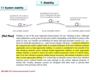
Download
1 / 80
810 likes | 963 Views
This presentation, led by Project Engineer Ms. Christina Stack, discusses the development and implementation of the Stability Augmented Steering System (SASS) for the T-45, aimed at addressing historical ground handling deficiencies. The project highlights the background, identification of problems related to aircraft handling, the innovative solutions introduced, rigorous testing phases, results achieved, and key lessons learned throughout the process. Acknowledgments are made to project team members for their contributions, emphasizing collaboration between the Navy, Boeing, and engineering experts.

E N D
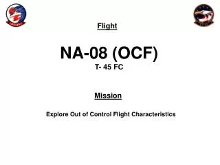
T-45 Stability AugmentedSteering System “The Goshawk Learns Some Basic Manners” 20 October 2005
T-45 Stability AugmentedSteering System Ms. Christina Stack Project Engineer
Many thanks to… LCDR Allen Blocker, USN Lead Project Officer Mr. Jim Reinsberg Lead Boeing Engineer, Designer and Developer of SASS Mr. David Klyde Systems Technology, INC Mrs. Marge Draper-Donley NAVAIR
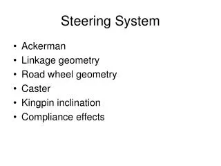
Chapter Overview • Background • Problem • Solution • Testing • Results • Lessons Learned
T-45 Background Info “In the beginning…”
T-45 Background Info …The Great Legislative Body declared, “Thou shalt take a foreign, land-based jet and remake it in thy naval image.”
T-45 Background Info We needed just one or two minor changes…
6” FIN CAP EXTENSION APPROACH IDLE STOP STANDARD ATTITUDE HEADING REFERENCE SYSTEM NEW EJECTION SEATS (NACES) ON BOARD OXYGEN GENERATING SYSTEM COMPOSITE STABILIZER REDESIGNED GLASS COCKPIT SMURF • SIMULATED • GUNNERY SYSTEM • HEADS UP DISPLAY • VCR ADD YAW DAMPER ADRS • NEW NOSE • STRUCTURE • NEW NLG • NOSE WHEEL STEERING • LAUNCH, HOLD BACK BARS TAIL HOOK • F-405-RR-401 • ADOUR ENGINE • 5845 LBS THRUST • EMI PROTECTION • BACK UP FUEL CONTROL CENTRAL VENTRAL FIN • NEW MAIN LANDING • GEAR AND STRUCTURE • IMPROVED BRAKES @3K ADDITIONAL STRUCTURE FOR CATAPULT/ARRESTMENT LEADING EDGE SLATTED WING T-45 Background Info
T-45 Background Info What could possibly go wrong?
JEEP Ground Handling History “The Saga of the T-45 All-Terrain Vehicle”
Ground Handling History • Aug 1992: Digital full time NWS incorporated. • May 1993: “Overly sensitive directional control characteristics during landing rollout.” – Part IK This deficiency will persist until 2004.
Ground Handling History Picture worth 1000 words…
Ground Handling History From 1992 to 2000, Averaged 2 accidents per year and Almost 1 Class A mishap per year Due to ground handling deficiencies
Understanding the Problem “If only Dale Ernhardt, Jr. could fly”
Ground Handling History But, in 1998… Navy and Boeing seek help of Systems Technology, Inc (STI) and NASA Or “That Other Space Agency,” depending on who you ask around Mojave, CA…
Understanding the Problem “They got skills!” Insert your tire here.
Understanding the Problem Results: • Tire models were in error; materials critical
Understanding the Problem Results: • Tire models were in error; materials critical Tires +
Understanding the Problem Results: • Tire models were in error; materials critical Tires + Landing gear mechanics and geometry +
Understanding the Problem Results: • Tire models were in error; materials critical Tires + Landing gear mechanics and geometry + Dynamic interactions =
Understanding the Problem Results: • Tire models were in error; materials critical Tires + Landing gear mechanics and geometry + Dynamic interactions = Aircraft response feels like an acceleration-command system and exhibits an “oversteer” condition
Understanding the Problem If you’re going to be in the ground handling business, you better get familiar with some terms and concepts: Cornering Stiffness Braking and Blown Tire Affects Hydroplaning Thermal Management Understeer Gradient
Heading Slip Angle a CG Velocity Vector • “Static” Understeer Gradient (UG) is a tire property…. • Positive = understeer, Negative = oversteer • Weak function of CG, ignores “artificial” stability. • Strong function of TIRES, “installation factors”, and aerodynamics (vertical load). • Cars are understeer for controllability; race cars are oversteer for agility • T45 is Oversteer Understanding the ProblemUndersteer Gradient
Oversteer: Right nose wheel steering (into the skid) cannot prevent “spin out” - “Icey”. (UG < 0.0) Understeer: Left nose wheel steering (into the turn) cannot prevent “plow out” (UG > 0.0) Note: Spin out and plow out occur when tires saturate (like “stall”) These are limit performance characteristics. Understanding the ProblemUndersteer vs. Oversteer
THIS is oversteer. Picture courtesy of Wally Pankratz Racing Photos http://www.starite.com/racing/wally_photos.htm
Understanding the Problem What can be done? Provisional Improvement Major Improvement Minor Improvement • Tier 1 • Tires • Yaw Rate feedback • to NWS • Tier 2 • NWS Freeplay • NWS Rate • NWS Servo • Tier 3 • LEAD-LAG* • Roll Stiffness • Ergonomics
The Solution The Stability Augmented Steering System Full-time yaw-rate feedback to the NWS.
SASS • Attempts to nullify yaw rates using NWS based on set gains that vary with airspeed K = gain constant; R = yaw rate; δNWS = NWS commanded KR = δNWS • 4 pilot-selectable gains were used for flight test
Power SASS Control Law Selector Switch “CLAWS” SASS
SASS Looking aft at rear cockpit Aft, left bulkhead SASS unit
New Metrics “Teaching an old dog new tricks”
New Metrics • Heading Angle Bandwidth (HABW) • Based on longitudinal flying qualities specifications • Runway Offset Capture and Hold (ROCH) • Traditional FQ parameter capture and tracking task • ROCH with Braking (ROCHB) • Increases difficulty of ROCH and more operationally representative
New Metrics • HABW • Defined as highest frequency at which you have less than 45° phase lag between rudder input and aircraft yaw response • Measured using rudder pedal frequency sweeps at discrete groundspeeds, described in rad/sec. • Demonstrates a pseudo-track of understeer gradient and PIO ratings Key: Wider is better!
New Metrics • 4 Selectable SASS Gains (rad/sec HABW*) • SASS-0: 1.0 - baseline aircraft • SASS-1: 2.0 • SASS-2: 2.5 • SASS-3 (Initial Testing): Starts as Baseline Aircraft • SASS-3 (Follow-On): 2.0 below 50kts; 2.5 above 70kts. Perform Rudder Sweeps for each gain at discrete speeds to measure HABW.
Intercept Angle = 5-7 o at 50kts, 4-6 o at 75kts, 3-5 o at 100kts 50ft offset Hold Adequate Overshoot +/- 5 ft Desired Overshoot +/- 2 ft Capture New Metrics • ROCH • 50 KGS, 75, and 100 KIAS discrete points
New Metrics • ROCHB Intercept Angle = 3-5 deg at 100kts When angle established, symmetrical braking at 0.15Nx until 50KGS while performing centerline control task. 50ft offset Hold Adequate Overshoot +/- 5 ft Desired Overshoot +/- 2 ft Capture
Test Planning “Are you sure this isn’t dangerous?”
Test Planning • Phase 1 • Concept proof and Gain selection • Metric and Modeling Validation • CV Suitability • Phase 2 • Hybrid Gain evaluation • Production Unit Verification • Phase 3 • Crosswind and wet runway • Operational Evaluation using Instructor Pilots
Test Planning • Crosswind and Wet Runway Tasks • Centerline Maintenance • Upwind / Downwind Captures • Max braking test points.
Sim Fam Flight TP w/in NATOPS limits Rudder Sweeps X ROCHs FAM 1 ROCHBs FAM 1 Crosswind Testing FAM 2 Crosswind Testing outside current NATOPS limit X Wet Runway Testing FAM 2 Wet Runway Testing outside current NATOPS limit X Test PlanningRisk Mitigation • Pilot Training
Test PlanningRisk Mitigation • Build-up • Increasing vs. Decreasing Airspeed • Worst control region from 60-80 knots • 50 knot points during high-speed taxi • 75 and 100 knot points during roll-and-go • Maneuvers Normal “navigational” inputs Rudder Sweeps ROCHs ROCHBs Operational Evaluations
Test PlanningRisk Mitigation • Runway Excursions (End vs. Side) • KIO Distance Criteria established • Off the End • 50knots to rotation then back to stop • Verbal “KIO” call over radio at marker • Nominal roll-and-go at each speed prior to test points for testable runway familiarization • Off the Side • 30 deg hazard pattern • Based on runway surveys
Test Planning 14 200-300’ Lens 5’ Mound 2’ Deep Control Box * Radar Tower 300’ from either runway 1300’ 6’ Deep * 6 24 1500’ 100’ 100’ Tree line Ditch 200’L x 6’D Pond 6’ Deep Center Field 300’ Lens 6-10’ Ditch w/ mound 6-10’ Ditch w/ mound = E-28 Cat Site MK 7 Site = 1000’ 32