Download
1 / 39
390 likes | 486 Views
Explore the development of FPGA-based electronics readout for construction trigger at Abilene Christian University, focusing on E906 experiment and SBIR Phase II. Implementation of detector upgrades and methodology refinement for improved statistics.

E N D
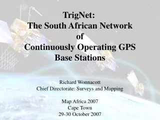
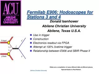
Donald Isenhower • Abilene Christian University • Abilene, Texas U.S.A. • Use in trigger • Construction • Electronics readout via FPGA • Attempt at 100% livetime trigger • Relationship between E906 and SBIR Phase II Fermilab E906: Hodoscopes for Stations 3 and 4 Slides are a compilation of many different talks at different places. Special thanks to Paul Reimer.
Experiment Runs Expt. Funded Magnet Design Experiment And construction Construction Proposed Jan. 2004 Publications 2005 2006 2007 2008 2009 2010 E906 Scheduling Plans in the Past Expt. Funded Magnet Design and construction Expt.. Construction Expt. runs Experiment Runs Expt. Funded Magnet Design Experiment And construction Construction Proposed Jan. 2004 Collider and MINOS running 906 Publications Publications 2006 2007 2008 2009 2010 2009 2005 2006 2007 2008 Donald Isenhower - ACU
Comparison of the two detectors:Fermilab E866/NuSea Detector 60m x 3m x 3m • Forward xF, high mass m-pair spectrometer • Liquid hydrogen and deuterium targets • Two acceptance defining magnets (SM0, SM12) • Also used solid W, Be, Fe targets • Beam dump (4.3m Cu) • Hadronic absorber (13.4 I0-Cu, C, CH2) • Momentum analyzing magnet (SM3) • Three tracking stations • Muon identifier wall & 4th tracking Donald Isenhower - ACU
E906 Apparatus(old open design) Replacement of old hodoscopes: • Stations 1 & 2 scintillator are being replaced because they are the wrong size and are too thin to produce enough light to deal with fringe fields of M1 and M2. • Stations 3 & 4 scintillators are being replaced because they are the wrong size and are old enough that they will craze very badly if any work is done on them. • There are also changes being made in order to improve the trigger. Donald Isenhower - ACU
E906 Spectrometer: Bend Plane View -- Old design Donald Isenhower - ACU
Comments on changes needed for detector sizes compared to original proposal for better statistics • Proposal contains tables of planned sizes of each detector. • Sizes change if z-position is changed (this is obvious). • But looking closer one finds something we missed. In the summer of 2007, Nathan Sparks (ACU), working with Paul Reimer and Chuck Brown, found out that ignoring events where a muon went through the coils was costing us acceptance. • Next slide shows effects of slight increases in detector size. It does not evaluate separately each detector component. It just scales every detector up in size by a specific fraction. Donald Isenhower - ACU
1,495 events pass through “normal” acceptance for x2>0.4 Add 10% --> 3,344 evts; Add 20% --> 5,168 evts; Add 50% --> 5,821 evts. Fine tuning of acceptance, tracking through M1 coils Work done by Nathan Sparks (ACU), summer 2007. Donald Isenhower - ACU
Some details on Stations 3 and 4 • Each plane will have 2x16 scintillators (split up/down or left/right). • Every paddle will be double ended (this is dictated by the trigger). • Each will be read out via an FPGA based TPC (design will borrow heavily from Pat McGaughey’s design for station 4 DCs). • TDCs will be multihit with 0.25ns resolution (easily done with even a low end FPGA (with a 100 MHz FPGA one can get approximately 0.04ns). • See proposal for details on how these were planned for the trigger. • Will be made from Eljen scintillator, each piece will be diamond milled (Eljen Corp. is about 60 km from Abilene, so they will be convient for us). Donald Isenhower - ACU
Details on EJ-200 Scintillator(note: Charles Hurlbut at Eljen is the one who founded Bicron’s plastic scintillator division and developed many of their scintillator materials) Donald Isenhower - ACU
Comments on ACU FPGA Programming Project • The U.S. government funds Small Business Innovative Research (SBIR) projects. Every funding agency must set aside ~1.5% of their budget for these projects. • DOE Nuclear Physics is of course one of these agencies. • Donald Isenhower and Shon Watson (ACU technician) are working with a new company called Innovation Partners and have just completed a Phase I ($100k) grant showing the feasability of a method to decrease the time to produce FPGA code. • A Phase II proposal ($750k) has been submitted to apply what was learned in Phase I to make viable product. It is planned to use E906 as the main nuclear physics experiment to produce a prototype that would perform as the readout for the hodoscope planes. • Hardware design will be based on work done by Pat McGaughey for the E906 drift chambers and the PHENIX Forward Vertex detector. Donald Isenhower - ACU
What is the problem? Figure 2 is not shown Donald Isenhower - ACU
Examples of FPGA coding method Donald Isenhower - ACU
Constant Fraction Discriminator The examples below were done using a set of ADC samples. Both discriminator functions were done via software in an FPGA. The CFD is a digital version of the analog circuit for a CFD. Donald Isenhower - ACU
Principal Component Analysis What is it? Donald Isenhower - ACU
Application to E906 ---> SeaQuest! Donald Isenhower - ACU
Principal Component Analysis Example Donald Isenhower - ACU
Note that this operation takes 93 clock cycles, but once started, you get a new result on every clock cycle. So each new PCA result would be produced in 2ns with a 500MHz FPGA Donald Isenhower - ACU
Why do we care about all this? • Almost every readout chain in E906 will be involve FPGAs. • FPGAs work as a pipeline for data, so in principle it should be possible to design a trigger with zero deadtime. • First level would come from hodoscopes. • Second level would come from other detectors. • Rutger’s presentation shows how things have changed and are being made simpler by new FPGA designs. In many cases an FPGA demo board is adequate for a DAQ system. • FPGAs are doubling in processing speed every year. LANL TDC boards have large number of channels at a very low cost. If SBIR Phase II is funded, we should be able to provide enough of these modules to read out all of the hodoscopes and be able to pass the information on to the Rutger’s trigger module. • Communication between modules is fast. Many FPGA’s now come with dual 2.5Gbit ethernet connections. Donald Isenhower - ACU
Rates from old designSolid Fe magnet shouldn’t be too different Expected single muon rates per 2£1012 protons from decay-in-flight mesons which pass through the detector ('s) and satisfy trigger matrix tracking requirements (Trks.) from liquid hydrogen and deuterium targets and the copper beam dump. Donald Isenhower - ACU
Conclusions • Hodoscope concerns have been greatly decreased with finds of PMTs and scintillator from old experiments by P.R. and N.M.. • Station 1 will be the most worrisome plane, primarily due to rates and occupancy level. If the paddles are too wide, they likely will be “on” for every proton bucket. • Single time bucket resolution appears to be simple for all cases. • Some attention needs to be paid to effects on increasing the number of hodoscope paddles from 2x16 per plane to 2x32 per plane at Station 1 and possibly Station 2. • Do we overlap hodoscope paddles? If so, by how much. Tradeoff is between rate limits and trigger capabilities. • Having double-ended readouts for Stations 3 and 4 should not now be a problem since we won’t need any of the old PMTs for Stations 1 and 2. Donald Isenhower - ACU
Extra Slides. Ignore. Donald Isenhower - ACU
Item Responsible Source Group Station 1 Hodoscopes scintillator ACU New phototubes ACU New readout ACU New Station 2 Hodoscopes scintillator ACU New phototubes ACU New readout ACU New Station 3 Hodoscopes scintillator ACU New phototubes ACU New readout ACU New Station 4 Hodoscopes scintillator ACU New phototubes ACU New readout ACU New
Simple DAQ Systems for FPIX2 FPGA Development at LANL PLM 12/11/06 We've assembled two DAQ systems to read out data from the FPIX2 through a Xilinx Virtex-4 FPGA development board. The goal was to use off the shelf components that require a minimum of programming to record the data. Optionally, the raw data is converted to a ROOT ntuple containing the hit row, column and amplitude value. We also have an Actel FPGA board that can be interfaced to these DAQ systems. Donald Isenhower - ACU
Figure 1. DAQ system for FPIX2 single chip test card using fast PC parallel ports Donald Isenhower - ACU
System 1. Provides ~1MB/sec sustained rate to disk/ntuple file. Three high-speed 8-bit parallel ports are used to read a 24-bit word from the FPGA, as shown in Figure 1. A control line from one port of the PC is used to clock the data from the output FIFO of the FPGA. The parallel ports can operate in PS/2 mode or EPP mode (which is about twice as fast). The software is very simple linux C code using direct I/O through the parallel ports. This system is adequate for measuring the FPIX noise, channel by channel, in about ten minutes. The software can also be compiled to run under windows. These PCI card based parallel ports are very inexpensive and easy to use. Data and clock lines are TTL, carried on regular ribbon cable. The FPGA output lines are set to 2.5 V CMOS. Interface connections between the FPGA, FPIX (single chip) and PC were bread-boarded using twisted pair and flat ribbon cabling. Donald Isenhower - ACU
Figure 2. DAQ system for FPIX2 eight chip test card using NI PCI-6534 card. Donald Isenhower - ACU
System 2. Provides ~80MB/sec for a 64MB 32 bit transfer to memory. The sustained rate to disk has not yet been measured. This system uses the National Instrument PCI-6534 digital I/O card, as shown in Figure 2. Up to 32 bits of data can be collected at 20 MHz using pattern I/O. The PCI card generates pulses that are used as before to clock the data out of the FIFO. Cabling is done with commercial shielded twisted pair cable. The clock line is 5V TTL, resistively terminated and attenuated to 2.5V at the FPGA. The FPGA outputs are 2.5 V CMOS. The software is very simple, written in C for Windows using National Instrument's DAQmx driver. Donald Isenhower - ACU
Figure 3. Interface card between FPIX 8 channel test card and Virtex 4 FPGA board. Top connector is attached through 50 pin .025 ribbon to FPIX. Bottom connector attaches to FPGA board. Donald Isenhower - ACU
We've used the PCI-6534 hardware to successfully read data at full speed from a 74F series TTL counter clocked at 20 MHz. We are presently connecting it to the FPGA board. This system appears capable of transferring data at the speed of existing PHENIX data collection modules. The PCI-6534 is somewhat expensive, costing about $2000 for the card and shielded cable. Interfacing between the FPIX (on an 8 chip HDI test card) and the FPGA was done with a 4 layer PCB adapter card and twisted pair cabling (Figure 3). The FPGA to PCI card interface was done with a 2 layer PCB and shielded cable (Figure 4). Donald Isenhower - ACU
Figure 2. Interface card between Virtex 4 FPGA board and cable to PCI-6534. Top connector is for shielded cable to PCI-6534 card. Bottom connector attaches FPGA board. Donald Isenhower - ACU