Download
1 / 9
90 likes | 178 Views
Detailed testing and analysis of chain of hybrid modules using various configurations and shunt controls to optimize performance and reduce noise interference. Suggestions for future improvements included.

E N D
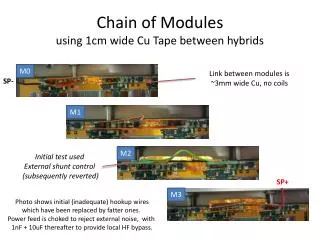
Chain of Modules using 1cm wide Cu Tape between hybrids M0 Link between modules is ~3mm wide Cu, no coils SP- M1 M2 Initial test used External shunt control (subsequently reverted) SP+ M3 Photo shows initial (inadequate) hookup wires which have been replaced by fatter ones. Power feed is choked to reject external noise, with 1nF + 10uF thereafter to provide local HF bypass.
Chain of Hybrids @ 5A (2144-3) Chain of Modules @ 9A (2182-3) – M2 using external shunt control DTN and ENC better on average, but not for every column
The Bigger Picture M2 now uses internal shunt control Caps here Choke on hookup wires (not to scale!)
Chain of Modules @ 9A (2186-3) – M2 using internal shunt control Chain of Modules @ 9A (2187-3) – M2 using internal shunt control, “column 3” shield ties added
Stavelet DTN @ 0.50fC 2187-11 : M0 at 0.5fC 2187-11 : M1 at 0.5fC Sum(hits): simply sum the number of hits shown in each double trigger plot 131 slices, each slice 100 events, each column 1280 channels 0 2 0 2 6 14 54 102
Stavelet DTN @ 0.50fC 2187-11 : M2 at 0.5fC 2187-11 : M3 at 0.5fC Sum(hits): simply sum the number of hits shown in each double trigger plot 102 10 3 49 20 63 80 346
Chain of Modules @ 9A (2188-19) – M2 SP+ link with 12nH inductor Chain of Modules @ 9A (2188-19) – M2 SP- link with 12nH inductor
Interpretation • CofM gives better DTN than CofH • No surprises • External shunt regulation of M2 gave better DTN and ENC results than internal regulation • Due to inductance of wired links between boards? • Due to location of regulation at power entry? • Due to higher Vdd? • Addition of “column 3” shield ties had no effect • No surprises • Adding 12nH inductor to SP+ inter-hybrid link improves DTN verys slightly • Same inductor in SP- inter-hybrid link does nothing
Ideas: what next? • Try a star point geometry • Remove the existing inter-module ties and instead bridge the current between modules using wires (or tape) soldered to the middle of the inter-hybrid copper tape links. • Should reduce HF currents on “odd” numbered hybrids (which have worse DTN). • If caps fitted at the star point, should also be better rejection of bus noise. • Does this make any sense? • Reduce loop area of hookup • Caps (10uF + 1nF) from each module to common HF return foil