Size Control Over Semiconducting Materials for Organic Electronics
130 likes | 274 Views
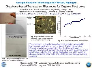
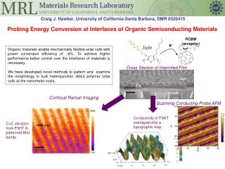
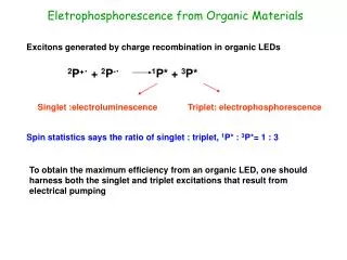
This project focuses on optimizing the size and structure of organic semiconducting nanowires to improve efficiencies in organic electronics, particularly in solar cells. Key techniques involve templating with aluminum oxide membranes for precision control of electron donor and acceptor materials. By increasing the interfacial surface area and enhancing molecular packing, we aim to boost charge transport. Future plans include structural characterization and the development of nanowire-based solar cells, aligning with current trends towards low-cost, flexible, and lightweight electronic solutions.

Size Control Over Semiconducting Materials for Organic Electronics
E N D
Presentation Transcript
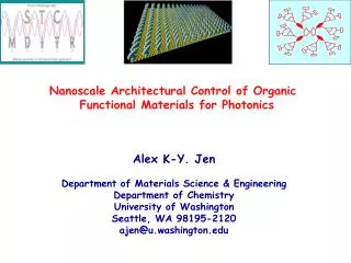
Size Control Over Semiconducting Materials for Organic Electronics CollenLeng1, Jeffrey M. Mativetsky1, John E. Anthony2, Yueh-Lin Loo1 Chemical and Biological Engineering, Princeton University Chemistry, University of Kentucky
Why Organic Electronics? • Low cost solution processing • Mechanical flexibility • Lightweight http://images.sciencedaily.com/2008/02/080206154631-large.jpg http://ww1.prweb.com/prfiles/2009/10/04/167139/FlexibleOrganicElectronicsdisplay.jpg
Increasing Efficiencies of Organic Solar Cells • Increase charge transport • molecular packing and orientation • Increase surface area between donor and acceptor materials
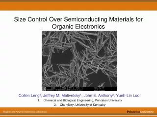
Project Goal Make organic semiconducting nanowires • Size control of electron acceptors and donors • Increase interfacial surface area • Wire-like structures for efficient charge transport Method: templating using aluminum oxide membranes • Scanning electron micrographs of aluminum oxide membrane Top view of membrane Cross-section of membrane Cross-section (zoomed in) 300 μm 2 μm 2 μm
Set-up • Allow solution to penetrate membrane from I-tube • Cap off I-tube to sustain internal pressure and prevent the solution from completely flowing through membrane rubber stopper closed air solution Electron donor: ethyl-TES-ADT I-tube membrane Teflon gasket Viton O-rings
Nanowires Inside Porous Membrane Cross-sectional views 15 μm 15 μm 10 μm 2 μm
Extracting Nanowires NaOH: dissolve membrane, free nanowires Options for removing NaOH and alumina: 1.Vacuum filtration 2. Centrifuge Nanowire mixture Viton O-rings Air out Polycarbonate filter Fritted glass
Extracted Nanowires Bundles of ethyl-TES-ADT nanowires Close-up of ethyl-TES-ADT nanowires 1 μm 10 μm
Nanowires on Glass High-density nanowires on glass: Close-up of wires: 30 μm 100 μm
TEM & Electron Diffraction Occasional polycrystalline structures Bundle of ethyl-TES-ADT nanowires in a transmission electron microscope (TEM) Electron diffraction of nanowires to the left shows some polycrystallinity
PCBM and P3HT Nanowires? Nanowires of other materials can be made. [6,6]phenyl-C61-butyric acid methyl ester (PCBM) nanowires: - the most commonly used electron acceptor 3 μm
Future Plans • Structural studies: • Thinner nanowires (10 - 20 nm diameters) to better match exciton diffusion lengths • Crystallization to help electron transport • Structural characterization (Grazing Incidence X-ray Diffraction) • Photovoltaic studies: • Map photoexcited charge generation at donor-acceptor nanowire interfaces (Kelvin Probe Force Microscopy, Photoluminescence) • Nanowire-based solar cells
Acknowledgements • Professor Loo • Jeff Mativetsky • Gerry Poirier • Loo Lab • PEI/Siebel Energy Grand Challenge