Download
1 / 38
380 likes | 601 Views
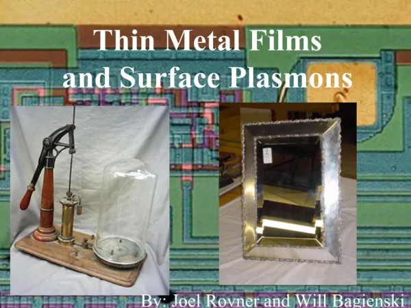
Surface Diffraction Studies of Organic Thin Films. Mehmet Fatih Dan ış man Middle East Technical University Department of Chemistry. Methanethiol Self-Assembled Monolayers (SAMs) on Au(111). Pentacene (C 22 H 14 ) Thin Films on Ag(111). Top view. Side view.

E N D
Surface Diffraction Studies of Organic Thin Films Mehmet Fatih Danışman Middle East Technical University Department of Chemistry
Methanethiol Self-Assembled Monolayers (SAMs) on Au(111) Pentacene (C22H14) Thin Films on Ag(111) Top view Side view Octadecyltrichlorosilane (OTS) SAMs on Silica
Advantages of helium atom diffraction • Low-energy (~14meV) He-atoms produced by supersonic expansion • λ≈1 Å comparable to unit cell dimensions • Sensitive only to topmost layer • Non-perturbing • Very sensitive to surface corrugation • Very sensitive to adsorbate coverage due to large cross-sections Real time monitoring of film growth
Experimental highlights and the diffraction chamber Tnozzle=70K dnozzle=20 μm P: 100 psi (~7 atm) • Main Beam Source kept at 70 K (Δv/v < 2%) • Diffraction data obtained at low surface temperature (40 K) Low level of inelastic scattering
i f a Diffraction from a surface For constructive interference path length difference should be equal to a multiple of wavelength. Bragg condition
Diffraction Geometry and the Ewald Sphere Construction -50 -30 -20 00 -40 -10 -31 Ewald Sphere kfz Laue Condition: Ki+G=Kf whereG=ma*+nb* m,n N denotes a reciprocal lattice vector kiz b* kf a* ki θf θi k00 ΔK Kf Ki ki = 5.1 Å-1 ΔK// = ki (sin θf – sin θi) ki = 2/
Self-Assembled Monolayers “Self-assembled monolayers (SAMs) are ordered molecular assemblies that are formed spontaneously by the adsorption of a surfactant with a specific affinity of its head group to a substrate.” F. Schreiber, Prog. Surf. Sci. 65, 151 (2000) J. C. Love et al., Chem. Rev. 105, 1103 (2005)
Why Methanethiol Monolayers on Au(111)? • What is the effect of intermolecular interactions on the adsorption geometry of alkanethiol self assembled monolayers (SAMs)? • Will the (3x23) will be observed for the shortest alkanethiol (CH3S) too? • What is adsorption site of the sulfur atom? • The bridge site as the DFT calculations predict • Or the atop site found experimentally by X-ray photoelectron diffraction and X-ray standing waves
We tackled the problem by using three different complementary probes to have a complete picture Helium and X-ray diffraction • Methanethiol forms a (3x4) superlattice (though after a complex deposition/annealing procedure) • A superlattice, although different from the (3x23) phase, exists even for the shortest thiol monolayer Interchain interactions are not essential for superlattice formation X-ray photoelectron diffraction, MD simulations • A dynamic equilibrium exists between bridge site adorption and a novel quasi-ontop site adsorption.
<11-2> <1-10> Diffraction scans taken along four different azimuthal angles. (=0°) corresponds to the <1-10> direction, and (=30°) corresponds to the <1-10> direction. Expected positions of (3x3) lattice points in the <1-10> (<1-10>) directions are indicated by dashed (dotted) lines. Expected diffraction peak positions for (3x4) () and (3x3) (■) lattices overlaid on the experimental data before misalignment correction (a) and after the correction (b). Au(111) diffraction peak positions are indicated by solid squares.
Grazing Incidince X-Ray Diffraction: Theory and Results (3/3,6/3) (7/3,5/3) incidence angle (degr.) (0,-3/3) (4/3,2/3) (2/3,4/3) (4/3,5/3) (2/3,1/3) (5/3,4/3) (1/3,2/3) Grazing incidence X-ray diffraction geometry X-ray penetration depth and specular reflection intensity as a function of incidence angle Observed reciprocal space map at ki=1.306 Å-1 and kz=0.13 Å-1. The radii of the circles correspond to the relative intensities of the Bragg peaks. Yellow, red and blue circles correspond to Au, (3x3) and (3x4) lattices. The black dots indicate the (3x23) reciprocal space lattice points for which no diffraction intensity could be measured. Measured Diffraction Intensity (arbitrary units) as a function of perpendicular momentum transfer L; circles experimental data, solid line best fit, (h,k) indexes refer to Au(111) unit cell
Theoretical fit Reliabilty factor, rf rf = 0 for perfect fit X-Ray Photoelectron Diffraction: Theory Electron elastic scattering factor for Ni. f:Scattering factor : Scattering angle,r: Distance between the emitter and the scatterer, : scattering phase shift a: Amplitudeof the photoemitted wavefield at the scatterer.Decreases exponentially due to inelastic scattering, thermal motion of the atoms and 1/r dependence of the wavefield. Hence the main contribution to the diffraction intensities, A(k)2, is made by the nearest neighbors of the emitter atom which makes X-ray photoelectron diffraction a local structural probe.
rf= 0.81 rf= 0.49 rf= 0.52 rf= 0.48 X-Ray Photoelectron Diffraction: Results PED fits (lines) to experimental data (circles) collected at S 2p3/2 peak. Energy scan is performed in normal emission in the range 250 – 630 eV. Polar scans are performed at 250 eV photon energy.
Why pentacene thin films ? Device characteristics Mobility, On/off ratio, Turn on voltage Structural and Morphological properties of the film Molecular orientation, Molecular packing, Grain boundaries, Defect concentration, Domain size, Contacts Substrate and Growth conditions Adhesion energy, Substrate temperature, Flux, Surface steps
a b c Pentacene film morphology and mobility Triclinic unit cell, with single cleavage plane; molecules in each ac plane have tilted herringbone structure C.D. Dimitrakopuolos and D.J. Mascaro, IBM J. Res. & Dev. 45, 11 (2001)
Small domains Domain size increases Big domains Pentacene film morphology at the gold electrode – SiO2 interface of a Thin Film Transistor Typical pentacene film morphology on SiO2 Mobility is limited by the charge carrier injection at the electrodes Dimitrakopoulos C.D., Adv. Mat., 2002, 14, 99
Effect of substrate properties and the growth parameters on the film morphology Reduced surface Oxidized surface Low deposition rates and high substrate temperatures result in larger domain sizes Larger domain size Dewetting Smaller domain size Layer by layer growth Pratontepa S. et al., Synthetic Metals 2004, 146, 387 Ruiz R. et al., Phys. Rev. B, 2003, 67, 125406
Heavy species is accelerated by seeding into a lighter carrier gas P0≈400 Torr PPen≈10-3 Torr Pb≈10-5 Torr Ekin≈5 eV for He Ekin≈0.4 eV for Kr Seeded supersonic molecular beam source vs. conventional vapor phase deposition Organic source material is evaporated at sublimation temperature either in UHV or in flux of carrier gas. kT≈0.05 eV
Indirect evidence obtained from photoluminescence measurements about the high quality of quaterthiophene films prepared by supersonic molecular beam deposition quaterthiophene • Using high kinetic energy molecules during the deposition results in sharper photoluminescence bands than those of the thicker films grown by conventional techniques. • As the kinetic energy of the molecules increase the bands get narrower Low defect density or different film structures? Iannotta S. et al., Appl. Phys. Lett. 76, 1845 (2000)
Pentacene growth on the “stepped” Ag(111) Specular Intensity vs. Exposure TS=200K Ekin≈5 eV Specularity of the clean Ag(111) surface 30% (surface miscut 0.56, av. terrace width 380 Å)
Pentacene growth on the “stepped” Ag(111) TS=200K Ekin ≈5 eV Monolayer and the multilayer have different structures
Effect of substrate temperature on film growth Monolayer, Ekin ≈5 eV Multilayer, Ekin ≈5 eV Competition between local and global annealing Optimum substrate temperature for multilayer growth is 200 K Poor structure at higher temperatures may be caused by dewetting
Ekin≈5 eV Ekin≈0.4 eV Effect of kinetic energy on the film growth Monolayer, TS=200 K Multilayer, TS=200 K Ekin≈5 eV Ekin≈0.4 eV Surface diffusion is activated by the extra kinetic energy. Improvement in multi layer structure.
Multilayer film structure Ex-situ X-Ray Reflectivity Multilayer, Ts=200K, Ekin ≈5 eV • Full lines indicate a periodicity of 6.1 Å along <11-2> direction • Dashed lines indicate a periodicity of 15.3 Å along <1-10> direction • X-ray peak indicates a periodicity of 3.72 Å along the z direction • The asymmetry indicated a flat lying monolayer structures with a thickness of 7.8 Å
a = 7.44 Å : b = 6.1 Å c = 16.5 Å Thin film on Ag(111) Side view 7.8 Å Proposed Model for the Thin Film Structure b a = 7.90 Å Bulk : b = 6.06 Å c = 16.01 Å a Top view Top view Side view Molecules in the film rest tilted on their long side and form a 2-D lattice which is very similar to the b-c face of the bulk lattice
We had to change the crystal and by chance end up with an almost flat surface that led us to study the effect of step density on the film growth Helium scattering intensity, relative to the main beam intensity () from Ag(111) surface with relatively high step density (,) from Ag(111) surface with very low step density along different azimuthal directions
Effect of step density and substrate quality on the film growth TS= 200K Ekin ≈5 eV • Specularity of the “stepped” Ag(111) surface 30% (surface miscut 0.56, av. terrace width 380 Å) • Specularity of the “flat” Ag(111) surface 90% (surface miscut < 0.1, av. terrace width > 2000 Å)
Effect of step density and substrate quality on the film growth TS= 200K Ekin ≈5 eV • Specularity of the “stepped” Ag(111) surface 30% (surface miscut 0.56, av. terrace width 380 Å) • Specularity of the “flat” Ag(111) surface 90% (surface miscut < 0.1, av. terrace width > 2000 Å)
Comparison with previous STM studies Increasing pentacene film coverage on Au(111) Unit cell size decreases as the coverage increases France et. al, Langmuir, 2003, 19, 1274
Reciprocal space map of structure “4” Diffraction scans are taken in a 180o azimuthal, , range with 5o increments (36 scans). The results are combined to obtain a contour plot of the reciprocal space shown in the right figure. Grid lines in the left plot and the dots in the contour map indicate the expected positions for 6.1x3 unit cell.
8.67 Å 17.6 Å <11-2> <1-10> Structural model of “4” and comparison with theory • Experimental data suggests a (6.1x3) unit cell • Close coupling calculations reproduce the data quite well for small K// values however the code should be refined in order to obtain a better fit for large K// values (convergence problem).
Effect of kinetic energy Monolayer <11-2> direction, Ts=200 K Multilayer <1-10> direction, Ts=200 K
Effect of substrate temperature and annealing on the film structure Diffraction scans of the multilayer as a function of substrate temperature along <11-2> direction
Temperature programmed desorption measurement performed by monitoring He specular reflection intensity The low temperature at 328 K corresponds to a desorption energy of 94 kJ/mol The higher temperature rise at 382 K corresponds to 109 kJ/mol
Conclusions For Ag(111) surface with relatively high step density • Optimum growth is achieved by using high kinetic energy molecules, at low substrate temperatures • Local annealing induced by the impact of high energy pentacene molecules has a decisive role in improving the growth: keeping the substrate temperature low, in fact, processes like de-wetting or disorder induced by the growth of different polymorphs are hindered • The monolayer and the multilayer have different structures, monolayer having a (6.1x3) lattice and the multilayer having a unit cell very similar to that of bulk crystal.
Conclusions For the extremely flat Ag(111) surface • While the film characteristics follow the same trend, as a function of substrate temperature, as the films grown on the stepped surface, increasing kinetic energy does not improve the film quality considerably. • The multilayer has a different structure and worse quality than that of the films grown on the stepped surface. • This is probably due to the missing of steps. On the high step density surface, step edges provide extra dimensionality and act as nucleation centers for the tilted multilayer molecules which result in a step flow growth.
What next ? • Integration of a mass spectrometer to the He Atom Diffraction system, to detect the speed of the organic molecules, in order to have a more precise measure of the kinetic energy. • Use vicinal surfaces in order to study the effect of step density on the film growth more systematically. • Integrate a commercial Quartz Crystal Microbalance to the He Atom Diffraction system in order to measure the flux of organic molecules independently. • Grow organic films on gold surfaces coated on Quartz crystals in order to measure the film coverage simultaneously by both Quartz Crystal Microbalance technique and He scattering.
Acknowledgements Middle East Technical University Prof. İlker Özkan, Prof. Metin Zora, Prof. Erdal Bayramlı Prof. Hüseyin İşçi, Sevil Güçlü Higher Education Board of Turkey (YÖK) Princeton University Prof. Giacinto Scoles Dr. Loredana Casalis, Dr. Bert Nickel Prof. Kevin Lehmann, Scoles and Lehmann Research Groups Brookhaven National Laboratory, National Syncrotron Light Source, X10B beamline staff Sincrotrone Trieste ALOISA beamline staff Penn State University Prof. David L. Allara, Prof. John V. Badding, Jacob Calkins