Download
1 / 35
350 likes | 444 Views
Beam Position Monitors FAC Review October 29-31, 2007. Stripline BPM Performance and AFE Modifications Cavity BPM Electronics BPM Digitizer Comparison. Stripline BPM Performance and AFE Modification. BPM Performance. Take data synchronized pulse-by-pulse

E N D
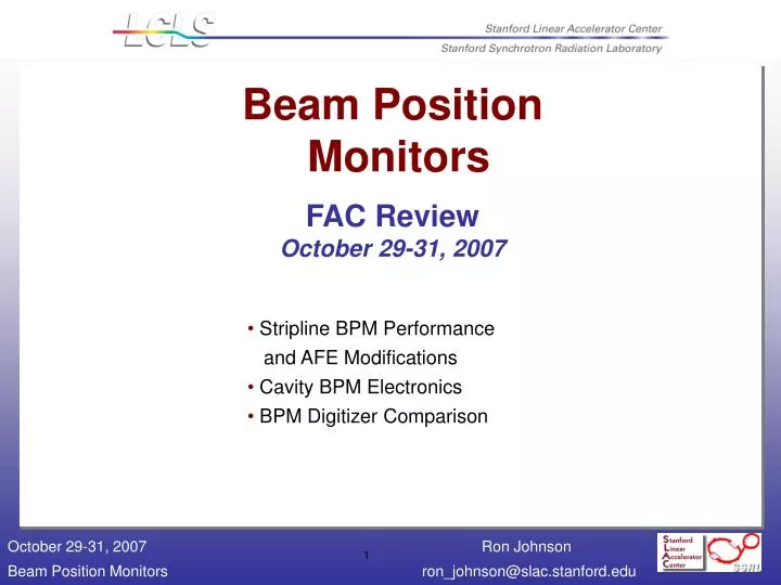
Beam Position MonitorsFAC ReviewOctober 29-31, 2007 • Stripline BPM Performance • and AFE Modifications • Cavity BPM Electronics • BPM Digitizer Comparison
BPM Performance • Take data synchronized pulse-by-pulse • Use linear prediction of each BPM from adjacent BPMS • Example: Compare bunch charge pulse-pulse 300 pulses 17 BPMs • Average rms/mean 0.0007 • May include pulse-pulse variation in losses
Performance • Predict BPM position reading from linear fit to adjacent BPMs (model-independent) • 300 machine pulses Effective beam charge 0.35 nC sx = 2.5 microns sy = 1.7 microns
BPM Performance • Q~ 200 pC • Resolution requirement is 10 microns for the small aperture BPMs • Meets resolution requirements
AFE Modifications • CAL – Additional switch to improve isolation • CAL – Add on/off control to oscillator • CAL – Replace BP filter with packaged unit • Chan – Replace 2nd attenuator with 0-31 dB unit • Chan – Put anti-alias BP filter on the PCB • Revise limiter • Revise layout and connectors
Status • Plan to build 53 modules for BSY/LTU/Dump. • Includes 3 spares for the injector. • And 3 modules for sector 24/25 (at the request of the commissioning team). Installation in January. • Most parts for AFE, PAD, and Clock Board on order (certainly long lead items). • Bulk of modules ready for installation in March/April.
Analysis • CW input from RF generator • Through 140 MHz bandpass filter to reduce generator harmonics • Digitize • Plot spectrum • Find apparent frequency from data • Fit sine curve to data • Look at residuals to fit • Compare phase noise
VME Digitizer @ -1 dBFS • Fit good to 6.5 ADC counts rms • ENOB = 11.5 • Harmonics <-80dBc
VME digitizer • PAD @ -1 dBFS • Fit good to 16 ADC counts rms • ENOB = 10.2 • Harmonics <-72dBc
Compare • Noise floor • Harmonic distortion • Other lines in spectrum • Input range
Digitizer Comparison • VME 5 dB better on noise floor • VME 8 dB better on worst harmonic
Comparison • Simplification • Reduces the number of accelerator ethernet ports, private ethernet ports, and DIGI ports. Communication with the ADC is over the VME backplane. • PAD would require enclosure and PS not yet designed. • Simplifies clock distribution (10 vs 18 dBm input) • Performance • Reduces broadband noise and harmonics. • FPGA has more computing power than the Coldfire. • Comparable data transfer rates ( measured 28 Mbytes/s for VME ADC). • Software • Both would need modification of the IOC software. • VME ADC needs a driver.
Status • Two VME ADC modules produced and tested. • Production of 40 additional modules to start in November. • Cable plant is designed and in CAPTAR. • Clock and LO distribution is being designed (Andrew Young). • Power supplies and power distribution is being designed (Steve Smith). • Hardware and software will be ready by April.
Calibration • Calibrate through BPM • Via stripline-stripline coupling • Performance not yet verified
Procedure • Calibrate with 2 mm scans: • LCLSscan_Horiz_Cal_200pc_2000um_VertOffset3mm_1_HighGain-2007-232-0820-131859.x.sdds • LCLSscan_Vert_Cal_200pc_2000um_VertOffset3mm_1_HighGain-2007-232-0820-131157.y.sdds • Check against other calibration scans • Analyze • LCLSscan_Vert_Cal_200pc_200um_VertOffset3mm_2_HighGain-2007-232-0820-161336.y.sdds • Take 1st 50 pulses to fix BPM-to-BPM alignment • Predict • X2 = linear combination of (X1, Y1, X3) • Y2 = linear combination of (X1, Y1, Y3) • For remaining events • Compare (X2, Y2) to predictions from (X1, Y1, X3, Y3) • All data taken at 200 pC charge
Check Calibration Scales • Analyze two more independent sets of calibration data • Confirms scale • Note apparent mover inconsistency for last step of X scan
Data Set • In middle of run beam (mover?) changes • Position jumps ~200 microns • Apparent beam angle changes • Study only first 150 pulses
X sx = 360 nm
Y sY = 270 nm
Resolution Conclusion • Both X & y resolution are below 500 nm • Movers are a pain • Beam jitter is troublesome • Requires large scans to get a calibration • Should move BPMs independently • Then beam jitter doesn’t affect calibration
Check Short Term Stability • Data: LCLSsynchlog_200pc_Horiz_00um_Vert_3000um_1_HighGain-2007-232-0820-132521.sdds • 1000 points at 6 Hz • Digitizer trigger glitch points removed • Y steering during first 30 points, ignore them • Alignment fit to next 50 points • Drift, resolution taken from remaining ~900 pulses • Resolution: sx =440 nm sY = 380 nm • Drift ~ 200nm in X, less than 100 nm in Y in 2.5 minutes
LCLSslowlog_1HourStab_4-2007-234-0822- 161515.sdds • 30 pulses every minute • 5345 pulses total ~ 3 hours • Many multi-mm jumps pulses 350 and 700 • Clock seems unlocked from 390 to 490 • Ignore first 700 pulses • Use next 150 pulses (5min) of data for alignment • Estimate resolution and drift from remaining pulses • Resolution: • sX = 1.6 microns • sY= 1.9 microns • Drift: • Look at fit residual plots • (Vertical axes are in mm) • ~5 microns in X • ~3 microns in Y • Over 2.5 hours • Biggest motions coincide with beam motion • (miscalibration) 3 Hour Cruise
Stability Conclusions • Stability results are almost good enough • Probably need better calibration • Maybe mechanical stability • Calibration is from 2 days prior to stability run • ???