Power Requirements for Next-Gen Wireless Systems
Explore the needs and solutions for improving power efficiency and reliability in 3G wireless systems, from higher data rates to solid-state arrays and vacuum electronic devices. Learn about amplifier linearity, reducing adjacent channel power, and combining power for peak performance.

Power Requirements for Next-Gen Wireless Systems
E N D
Presentation Transcript
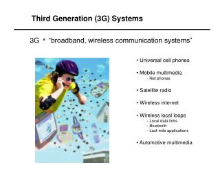
Third Generation (3G) Systems 3G “broadband, wireless communication systems” • • Universal cell phones • Mobile multimedia • - Net phones • Satellite radio • Wireless internet • Wireless local loops • - Local data links • - Bluetooth • - Last-mile applications • Automotive multimedia
Some Needs for 3G Wireless Average Power(W) Frequency Now Needed BackoffApplication Cellular 0.8 GHz 100 600 MCPA cellular 1.9 GHz 40 ≥2008-10 dBIMT-2000 PCS 2.1 GHz 40 100-200 8-10 dB IMT-2000 Satellite 2.3 GHz 125 4000 0 Satellite Radio 12 GHz 125 200-400 0 DirecTV Mobile 2.3 GHz 200 650 6 dB SatRad repeaters 2.6 GHz 20 200 10 dB MMDS
More Power….why? • Higher data rates - higher bit transfer rates - increase symbol transfer rate with complex encription (16QAM, etc) - broadband modulation schemes (CDMA, OFDM) require high peak power • Improved amplifier linearity - lower adjacent channel power - increased backoff off from peak power capability (more linearity and higher peak-to-average ratio for CDMA &OFDM) - feed forward linearization (make up for increased losses) • Improved availability and reliability - ability to compensate for weather (rain) - ability to handle partial component failure (and still broadcast)
Higher Data Rates Bit Error Rate for several modulation types • For fixed error rate, the energy per bit is fixed • Higher data rates (more bits per second) require higher power • Higher symbol rate requires higher energy per bit, which corresponds to higher power
Crest Factors for Spread-Spectrum Signals Broadband, spread-spectrum signals have high peak to average ratios (high “crest-factors”) AWGN waveform • Advanced modulation techniques cause higher peak to average ratios due to “phase add up” • For a given average power, these waveforms require higher peak power
Adjacent Channel Power Intermodulation Distortion 2-Tones • Multi-tone operation produces intermodulation distortion (IMD) • Intermodulation products cause adjacent channel power problems 8-Tones
Adjacent Channel Power Reduction Backoff from non-linear region Running amplifiers backed off from saturation for linearity (lower adjacent channel power) requires higher peak power Improve IMD
Adjacent Channel Power Reduction Multi-Channel Power Amplifier (with feed-forward circuit) TWT TWT with feedforward
Solid State rf Devices • Solid state device frequency and power • New developments driven by communications needs • Single device power level still insufficient (6 dB backoff from 50 W is only about 10 W per transistor) • How do we get more power?
Power Combining • Solid state devices have limited gain and power capability per device • Use series and parallel arrays to produce gain and power Power combined arrays are required (≈10 dB per device) • Broadband produces high peak electric fields • Many devices needed to avoid breakdown damage
Solid-State Arrays - Issues • Combiner losses are significant for large numbers of devices - ultimately adding more devices doesn’t give more power • Reliability of an array (many-components) - failures from transients, junction avalanche, overdrive, high VSWR, etc. • Aging of solid state devices - metal migration at high current density and high junction temperature - corrosion of intermetal contacts - thermal fatigue “Aging” produces: - transconductance decrease - threshold voltage changes - resistance changes - operating point changes (impedance change) - power and gain degradation Example: two devices in a Wilkinson power combiner power output decreases directly with impedance change
The Solution - VED Vacuum Electronic Devices Tubes work everywhere within this box • Traveling wave tubes and klystrons are used in ≥90% of the satellite communcation applications with demonstrated life and reliabilitywell in excess of solid state amplifiers!
Amplifier Efficiency TWTs are much more efficient than solid state amplifiers All data points are for multi-channel PCS amplifiers with feedforward linearization and -70 dBc IMD
Amplifier Linearity Highest Power LDMOS PCS Solid State Devices Solid state devices and tubes have similar linearity, but tubes have significantly higher power capabilities!
Satellite Radio Systems Satellite Transmitter Estimated link budget Power combined array of 48 TWTs produces ≥4 kW of radiated power
Power combining of TWTs Power combining of two TWTs P = 0.5[P1 + P2 + 2(P1 P2 )1/2 cos Df Depends on power and phase balance (10 deg of phase or 2 dB in power exceeds Magic-T losses) Amplitude Phase
Phase Variability of TWT array Phase versus input drive measured for 35 TWTs • The power loss in the array of TWTs is proportional to cos Df • Using the phase deviation from the mean, the total power loss at saturation is about 0.1% • Measured phase distribution creates negligible power loss
Gain Variability of TWT array Gain versus input drive measured for 35 TWTs Gain distribution ±0.5 dB at saturation Produces very small power variation Gain change with time for different types of TWTs Gain is stable after sufficient burn-in time D.M.Goebel, “Theory of Long Term Gain Growth in Traveling Wave Tubes, IEEE Transactions on Electron Devices, 42 (2000) p.1286.
Power Combining Results • 3G telecommunications applications require operation 6 to 10 dB backed off from saturation for linearity, but spread spectrum signals still sample saturation due to high “crest factor” • Phase and gain variations were measured for 35 Model 5525H TWTs operated 6 dB backed off from saturation • Arrays of these TWTs with ≤5˚ phase variation and ≤1 dB gain variation at saturation produce negligible power combining losses (≤0.2%) • Primary losses at low power are in the combiners (Wilkenson, hybrids), and the primary cost at high power is in the waveguide combiners
Conclusion Many 3G applications need higher transmit power at higher frequency, in addition to other features like linearity, high efficiency, low cost, etc. “The requirements for a high power and higher frequency technology continue to point obstinately in the direction of the vacuum device.” S.C. Cripps, RF Power Amplifiers for Wireless Communication, Artech (1999)