Novel Approaches to Fine-Grained Thread Migration for Chip Communication Optimization
This paper explores the concept of fine-grained thread migration to reduce on-chip data movement, introducing hardware-level implementations for efficient migration and memory access models. The goal is to optimize chip communication and energy efficiency in multicore architectures.

Novel Approaches to Fine-Grained Thread Migration for Chip Communication Optimization
E N D
Presentation Transcript
The Execution Migration Machine 陳品杰 Department of Electrical Engineering National Cheng Kung University Tainan, Taiwan, R.O.C
Introduction(1/3) • Reducing on-chip traffic, is becoming critical to keeping CMPs within a manageable power envelope. • With threads effectively pinned to specific cores for most of their execution, a lion’s share of the on-chip traffic consists of data being brought to the core that uses it. • An alternative, which we explore in depth in this paper, is to allow threads to move around the chip as necessary to take advantage of a computation’s spatiotemporal locality(slide 5). • When the migration is sufficiently fine-grained and the latency low enough, we argue, judicious thread migration can significantly reduce on-chip bit movement
Introduction(2/3) • The novel contributions of this paper are as follows: • Fine-grained hardware thread migration • Our pure hardware implementation can accomplish a single thread migration in as few as 4 cycles between the closest cores when the minimum context is migrated, and 33 cycles between the farthest on our110-core grid with the maximum possible thread context • Instruction-granularity migration prediction • For statically discoverable patterns, our compiler can annotate memory instructions as either remote-access or migratory. • For access patterns that are difficult to discover statically (or that change at runtime), our implementation employs a hardware-level learning migration predictor to detect and respond to locality patterns
Introduction(3/3) • The novel contributions of this paper are as follows: • Stack architecture for partial context migration • Always moving the entire thread context can be wasteful if only a portion of it will be used at the destination core. • To further reduce communication, our cores implement a stack-based architecturewhere a migrating thread can take along onlyas much of its context as is required by only migrating the top of the stack. • Our migration predictor implementation takes advantage of this by learning the best context size for every migration. • To ensure a simple programming model, the in-core stack registers are backed by memory and automatically spilled or refilledas necessary without user intervention.
Architectural-level thread migration(1/5) • Motivation • When large data structures that do not fit in a single cache are shared by multiple threads or iteratively accessed even by a single thread, the data are typically distributed across multiple shared cache slices to minimize expensive off-chip accesses. • This raises the need for a thread to access data mapped at remote caches often with high spatiotemporal locality, which is prevalent in many applications; for example, a database request might result in a series of phases, each consisting of many accesses to contiguous stretches of data. • Temporal locality, refers to the reuse of specific data, and/or resources, within a relatively small time duration. • Spatial locality, refers to the use of data elements within relatively close storage locations.
Architectural-level thread migration(2/5) • Motivation • In a large multicore architecture without efficient thread migration, this pattern results in large amounts of on-chip network traffic. • Each request will typically run in a separate thread, pinned to a single core throughout its execution • Because this thread might access data cached in last-level cache slices located in different tiles, the data must be brought to the core where the thread is running.
Architectural-level thread migration(3/5) • Motivation • For example, in a directory-based architecture, the data would be brought to the core’s private cache, only to be replaced when the next phase of the request accesses a different segment of data (see Figure 1a, slide 9) • in an architecture based on remote cache access, each request to non-local data would result in a request-response pair sent across the on-chip interconnect • Because much of the dynamic powerin large multicores is consumed in the interconnect, these data movement patterns incur a significant power cost.
Architectural-level thread migration(4/5) • Motivation • If threads can be efficiently migrated across the chip, however, the on-chip data movement—and with it, energy use can be significantly reduced. • Instead of transferring data to feed the computing thread, the thread itself can migrate to followthe data (see Figure 1b, slide 9); • if the thread context is small compared to the data that would otherwise be transferred, moving the thread can be a huge win. • In the remainder of this section we argue that these requirements call for a simple, efficient hardware-level implementation of thread migration at the architecture level, and outline a memory access model which makes thread migration automatic and transparent to the programmer
Architectural-level thread migration(5/5) Remote access only Figure 1: When applications exhibit data access locality, efficient thread migration can turn many round-trips to retrieve data into a series of migrations followed by long stretches of accesses to locally cached data.
Architectural-level thread migration • The need for efficient thread migration • Moving thread execution from one processor to another has long been a common feature in operating systems. This OS mediated form of migration, however, is far too slow to make migrating threads for more efficient cache access viable: just moving the thread takes many hundreds of cycles at best. • We see fine-grained thread migration as an enabling technology; since the range of applications of this technique is necessarily limited by migration performance, we focus primarily on minimizing migration latency and the incurred on-chip interconnect traffic.
Architectural-level thread migration(1/5) • The elements of efficient thread migration • The implementation we describe here achieves very low migration latency by migrating the thread contextdirectlyfrom the core onto the interconnect network. • Threads migrate autonomouslyand directly into their target cores: • there are no centralized thread storage facilities, and there is no central migration arbiter. • This means that a single migration only incurs the delay of one core-to-core message, without the round-trip messages that would arise in a centrally coordinated system.
Architectural-level thread migration(2/5) • The elements of efficient thread migration • Each of our chip’s cores contains two separate thread contexts: a native context and a guest context. • A core’s native context may only execute the thread that originated on the core; the guest contexts serve all other threads, and evict threads back to their native cores if too many threads contend for the guest context. • Together with a separate on-chip network for threads returning to their native cores, this avoids protocol-level deadlock because the native core can always accept a returning thread
Architectural-level thread migration(3/5) • The elements of efficient thread migration • To further improve migration performance, our implementation can reduce migration message sizes by migrating just enough of the thread context to perform its task on the destination core. • To simplify hardware support for this partial context migration, our chip follows a custom stack-machine ISA • In this scheme, a thread migrating out of its native core can bring along only a few entries from the top of the stack; • the minimum useful migration size on our chip fits into two 64-bit flits. • Our implementation of partial migration is robust: • if the migrating thread broughtalong too few or too many entries, it is automatically transferred to its native core to access them.
Architectural-level thread migration(4/5) • The elements of efficient thread migration • The final component of efficient migration is deciding when the thread should migrate. • Our design uses a learning migration predictor to migrate only when the reduction in on-chip network traffic is likely to outweigh the migration costs.
Architectural-level thread migration(5/5) • Flits: Large network packets are broken into small pieces called flits (flow control digits) • Thefirst flit, called the header flit holds information about this packet's route (namely the destination address) and sets up the routing behavior for all subsequent flits associated with the packet. • The head flit is followed by zero or more body flits, containing the actual pay load of data.
Architectural-level thread migration (1/5) • Shared memory: an application of thread migration • Memory traffic, which in shared-memory designs constitutes a lion’s share of on-chip interconnect traffic, is very sensitive to migration costs, and therefore provides a good target for optimization. • For simplicity and scalability, we implemented a remote cache access (RA) shared memory paradigm as our baseline. • In this scheme, each load or store access to an address cached in a different core incurs a word-granularity round-trip message to the tile allowed to cache the address, and the retrieved data is never cached locally (the combination of word-level access and no local caching ensures correct memory semantics).
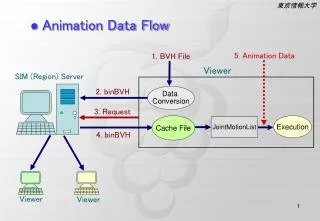
Architectural-level thread migration (2/5) • Shared memory: an application of thread migration • As in traditional NUCA(Non-Uniform Cache Architecture)architectures, each address in the system is assigned to a unique core where it may be cached: the physical address space in the system is partitioned among the cores, and each core is responsible for caching its region. This makes it easy to compute which tile can cache the data. • In addition to remote cache access, our design can automatically turn contiguous sequences of remote cache accesses into migration to the core where the data is cached followed by a sequence of local accesses. • For each access to memory cached on a remote core, an instruction-address-based decision algorithm (see Migration prediction) determines whether the thread should migrate or execute a remote access (see Figure 2).
Architectural-level thread migration (3/5) Figure 2: In our proof-of-concept implementation, shared memory leverages a combination of remote access and thread migration. Memory accesses to addresses not assigned to the local core can either result in a remote cache access or cause the execution context to be migrated to the relevant core.
Architectural-level thread migration (4/5) • The protocol for accessingaddress A by thread Texecutingon core C is as follows: • 1. compute the home core H for A • 2. if H = C (a core hit), • (a) forward the request for A to the cache hierarchy (possibly resulting in a DRAM access); • 3. if H != C (a core miss), and the predictor indicates remote access, • (a) send a remote access request for address A to core H, • (b) when the request arrives at H, forward it to H’s cache hierarchy • (c) when the cache access completes, send a response back to C, • (d) once the response arrives at C, continue execution.
Architectural-level thread migration (5/5) • The protocol for accessingaddress A by thread Texecutingon core C is as follows: • 4. if H != C (a core miss), and the predictor indicates migration, • (a) interrupt the execution of the thread on C, • (b) migrate the microarchitectural state to H via the on-chip interconnect: • i. if H is the native core for T, place it in the native context slot; • ii. otherwise: • A. if the guest slot on H contains another thread T’, evict T’ to its native core N’ • B. move T into the guest slot for H; • (c) resume execution of T on H, requesting A from its cache hierarchy (and potentially accessing DRAM).
The EM2 Architecture (1/2) Figure 3: The 110-core EM² chip layout
The EM2Architecture (2/2) • System architecture • The chip we evaluate in this paper consists of 110 homogeneous tiles placed on a 10×11 grid, connected via an on-chip network. • Substitute a DRAM interface, our test chip exposes the two networks that carry off-chip memory traffic via a programmable rate-matching interface; this, in turn, connects to a maximum of 16GB of DRAM via a controller implemented in an FPGA. • Tiles are connected by six independent on-chip networks: • two networks carry migration/eviction traffic, another two carry remote-access requests/responses, and a further two external DRAM requests/responses; • in each case, two networks are required to ensure deadlock-free operation
The EM2 Architecture(1/5) • Stack-based core architecture Figure 4: The processor core consists of two contexts in an SMT configuration, each of which comprises two stacks and a program counter, while the cache ports, migration network ports (not shown), and the migration predictor (not shown) are shared between the contexts. Stacks of the native context are backed by the data cache in the event of overflow or underflow.
The EM2 Architecture(2/5) • Stack-based core architecture • To simplify the implementation of partial context migration and maximally reduce on-chip bit movement, therefore, EM² cores implement a custom 32-bit stack-based architecture (cf. Figure 4). • Since the likelihood of the context being necessary increases toward the top of the stack from the nature of a stack-based ISA, a migrating thread can take along only as much of its context as is required by only migrating the top part of the stack. • Furthermore, the amount of the context to transfer can be easily controlled with a single parameter, which is the depth of the stack to migrate (i.e., the number of stack entries from the top of the stack).
The EM2 Architecture(3/5) • Stack-based core architecture • To reduce CPU area, the EM² core contains neither a floating point unit nor an integer divider circuit. • The core is a two-stage pipeline with a top-of-stack bypass that allows an instruction’s arguments to be sourced from the previous instruction’s ALU outputs. • Each context has two stacks, main and auxiliary: most instructions take their arguments from the top entries of the main stack and leave their result on the top of the main stack, while the auxiliary stack can only be used to copy or move data from/to the top of the main stack; special instructions rearrange the top four elements of the main stack. • The sizes of the main stack and the auxiliary stack are 16 and 8 entries.
The EM2 Architecture(4/5) • Stack-based core architecture • On stack overflow or underflow in the native context, the core automatically spills or refills the stack from the data cache; in a sense, the main and auxiliary stacks serve as caches for larger stacks stored in memory. • In a guest context, on the other hand, stacks are not backed by memory (cf. Figure 4); stack overflow or underflow at a guest context, therefore, cause the thread to migrate back to its native context where the stacks can be spilled or refilled.
The EM2 Architecture(5/5) • Stack-based core architecture • To ensure deadlock-free thread migration in all cases, the core contains two thread contexts that execute in SMT(Simultaneous Multithreading) fashion, called a native context and a guest context. • Each thread has a unique native context where no other thread can execute; when a thread wishes to execute in another core, it must execute in that core’s guest context. • Functionally, the two contexts are nearly identical; the differences consist of the data cache interface in the native context that supportsstack spills and refills, and the thread eviction logic and associated link to the on-chip eviction network in the guest context.
The EM2 Architecture (1/6) • Thread migration implementation • Whenever the thread migrates out of its native core, it has the optionof transmitting only the part of its thread context that it expects to use at the destination core. • In each packet, the first (head) flit encodes the destination packet length as well as the thread’s ID and the program counter, as well as the number of main stack and auxiliary stack elements in body flits that follow. • The smallest useful migration packet consists of one head flit and one body flit which contains two 32-bit stack entries. • Migrations from a guest context must transmit all of the occupied stack entries, since guest context stacks are not backed by memory.
The EM2Architecture (2/6) • Thread migration implementation • Figure 5: Hardware-level thread migration via the on-chip interconnect. Only the main stack is shown for simplicity. • Hop: one portion of the path between source and destination
The EM2Architecture (3/6) • Thread migration implementation • Figure 5 illustrates how the processor cores and the on-chip network efficiently support fast instruction-granularity thread migration. • When the core fetches an instruction that triggers a migration (for example, because of a memory access to data cached in a remote tile), the migration destination is computed and, if there is no network congestion, the migration packet’s head flit is serialized into the on-chip router buffers in the same clock cycle. • While the head flit transits the on-chip network, the remaining flits are serialized into the router buffer in a pipelined fashion.
The EM2Architecture (4/6) • Thread migration implementation • Once the packet has arrivedat the destination NoC router and the destination core context is free, it is directly deserialized; the next instruction is fetched as soon as the program counter is available and the instruction cache access proceeds in parallel with the deserialization of the migrated stack entries. • In our implementation, assuming a thread migrates H hops with B body flits, the overall thread migration latency amounts to 1 + H + 1 + B cycles from the time a migrating instruction is fetched at the source core to when the thread begins execution at the destination core. • Hop: one portion of the path between source and destination
The EM2Architecture (5/6) • Thread migration implementation • In the EM² chip, H varies from 1 (nearest neighbor core) to 19(the maximum number of hops for 10×11 mesh), and B varies from 1 (twomain stack entries and no auxiliary stack entries) to 12 (sixteen main stack entries and eight auxiliary stack entries, two entries per flit); • this results in the very low migration latency, ranging from the minimum of 4 cycles to the maximum of 33 cycles (assuming no network congestion).
The EM2Architecture (6/6) • Thread migration implementation • While a native context is reserved for its native thread and therefore is alwaysfree when this thread arrives, a guest context might be executing another thread when a migration packet arrives. • In this case, the newly arrived thread is buffered until the currently executing thread has had a chance to complete some (configurable) number of instructions; then, the active guest thread is evicted to make room for the newly arrived one. • During the eviction process the entire active context is serialized just as in the case of a migration (the eviction network is used to avoid deadlock), and once the last flit of the eviction packet has entered the network the newly arrived thread is unloaded from the network and begins execution.
The EM2 Architecture (1/3) • Migration prediction Figure 6: Each core has a PC-based migration predictor. When a specific instruction is first inserted into the predictor, the stack transfer sizes for the main and auxiliary stack are set to the default values of 8 (half of the main stack) and 0, respectively.
The EM2Architecture (2/3) • Migration prediction • To detect sequences suitable for migration, each EM² core includes a learning migration predictor —a program counter (PC)-indexed, direct-mapped data structure shown in Figure 6. • In addition to detecting migration-friendly memory references and making a remote-accessversus migration decision for every non-local load and store as in, our predictor further reduces on-chip network traffic by learning and deciding how much of the stack should be transferredfor every migrating instruction.
The EM2Architecture (3/3) • Migration prediction • The predictor bases these decisions on the instruction’s PC. • In most programs, sequences of consecutive memory accesses to the same home core and context usage patterns within those sequences are highly correlated with the instructions being executed, and those patterns are fairly consistent and repetitive across program execution. • Each predictor has 32 entries, each of which consists of a tag for the PC and the transfer sizes for the main and auxiliary stacks.
The EM2 Architecture (1/2) • Migration prediction- Detecting contiguous access sequences • Initially, the predictor table is empty, and all instructions are predicted to be remote-access. To detect memory access sequences suitable for migration, the predictor tracks how many consecutive accessesto the same remote core have been made, and, if this count exceeds a (configurable) threshold θ, inserts the PCof the instruction atthe start of the sequence into the predictor. • To accomplish this, each thread tracks • (1) home, which maintains the home location (core ID) for the memory address being requested, • (2) depth, which counts the number of contiguous times made to an address cached at the core identified by the home field, and • (3) start PC, which tracks the PC of the first instruction that accessed memory at the core identified by home.
The EM2 Architecture (2/2) • Migration prediction- Detecting contiguous access sequences • When a thread T executes a memory instruction for address Awhose PC is P, it must • 1. find the home core H for A; • 2. if home = H (i.e., memory access to the same home core as that of the previous memory access), • (a) if depth < θ, increment depth by one; • (b) otherwise, if depth = θ, insert start PC into the predictor table; • 3. if home != H (i.e., a new sequence starts with a new home core), • (a) if depth < θ, invalidate any existing entry for start PC in the predictor table (thus making start PC non-migratory); • (b) reset the current sequence counter (i.e., home ← H, start PC ← P, depth ← 1).
The EM2 Architecture (1/4) • Migration prediction- Migration prediction for memory accesses Figure 7: Decision/Learning mechanism of the migration predictor
The EM2Architecture (2/4) • Migration prediction- Migration prediction for memory accesses • When a load or store instruction attempts to access an address that cannot be cached at the core where the thread is currently running (a core miss), the predictor uses the instruction’s address (i.e., the PC) to look up the table of migrating sequences. • If the PC is in the table, the predictor instructs the thread to migrate; otherwise, to perform a remote access. • When the predictor instructs a thread to migrate from its native core to another core, it also provides the number of mainand auxiliary stack entries that should be migrated (cf. Figure 7a). • Because the stacks in the guest context are not backed by memory, however, all valid stack entries must be transferred (cf. Figure 7b).
The EM2Architecture (3/4) • Migration prediction- Migration prediction for memory accesses • To learn how many stack entries to send when migrating from a native context at runtime, the native context keeps track of the start PC that caused the last migration. • When the thread arrives back at its native core, it reportsthe reason for its return: when the thread migrated back because of stack overflow (or underflow), the stack transfer size of the corresponding start PC is decremented (or incremented) accordingly (cf. Figure 7c). • In this case, less (or more) of the stack will be brought along the nexttime around, eventually reducing the number of unnecessary migrations due to stack overflow and underflow.
The EM2Architecture (4/4) • Migration prediction- Migration prediction for memory accesses • The returning thread also reports the number of local memory instructions it executed at the core it originally migrated to. • If the thread returns withouthaving made θ accesses, the corresponding start PC is removed from the predictor table and the access sequence reverts to remote access (cf. Figure 7d). • This allows the predictor to respond to runtime changes in program behavior.
The EM2 Architecture • Custom stack ISA - stacks • Each core context contains a main stack (16 entries) and an auxiliary stack (8 entries), and instructions operate the top of those stacks much like RISC instructions operate on registers. • Conceptually, the stacks are infinite and the entries that are not stored in the core are kept in memory; on stack overflow or underflow, the core automatically accesses the data cache to spill or refill the core stacks. • Stacks naturally and elegantly support partial context migration, since the topmost entries which are migrated as a partial context are exactly the ones that the next few instructions will use.
The EM2 Architecture • Custom stack ISA - Computation and stack manipulation • The core implements the usual arithmetic, logical, and comparison instructions on 32-bit integers. • Those instructions consume one or two elements from the main stack and push their results back there. • Instructions in the push class place immediate on the stack, and variants that place the thread ID, core ID, or the PC on top of the stack help effect inter-thread synchronization. • Access to deeper stack entries can be achieved via instructions that move or copy the top of the main stack onto the auxiliary stack and back. The copying versions of the instructions make it easy to keep values like base addresses on the auxiliary stack.